
Material delivery pump
A technology for conveying pumps and materials, which is applied in the field of environmental protection dredging equipment, can solve the problems of environmental pollution, high cost, low efficiency, etc., and achieve the effect of good use effect and long service life
- Summary
- Abstract
- Description
- Claims
- Application Information
AI Technical Summary
Problems solved by technology
Method used
Image

Examples
Embodiment Construction
[0011] Below in conjunction with accompanying drawing and specific embodiment the present invention is described in further detail:
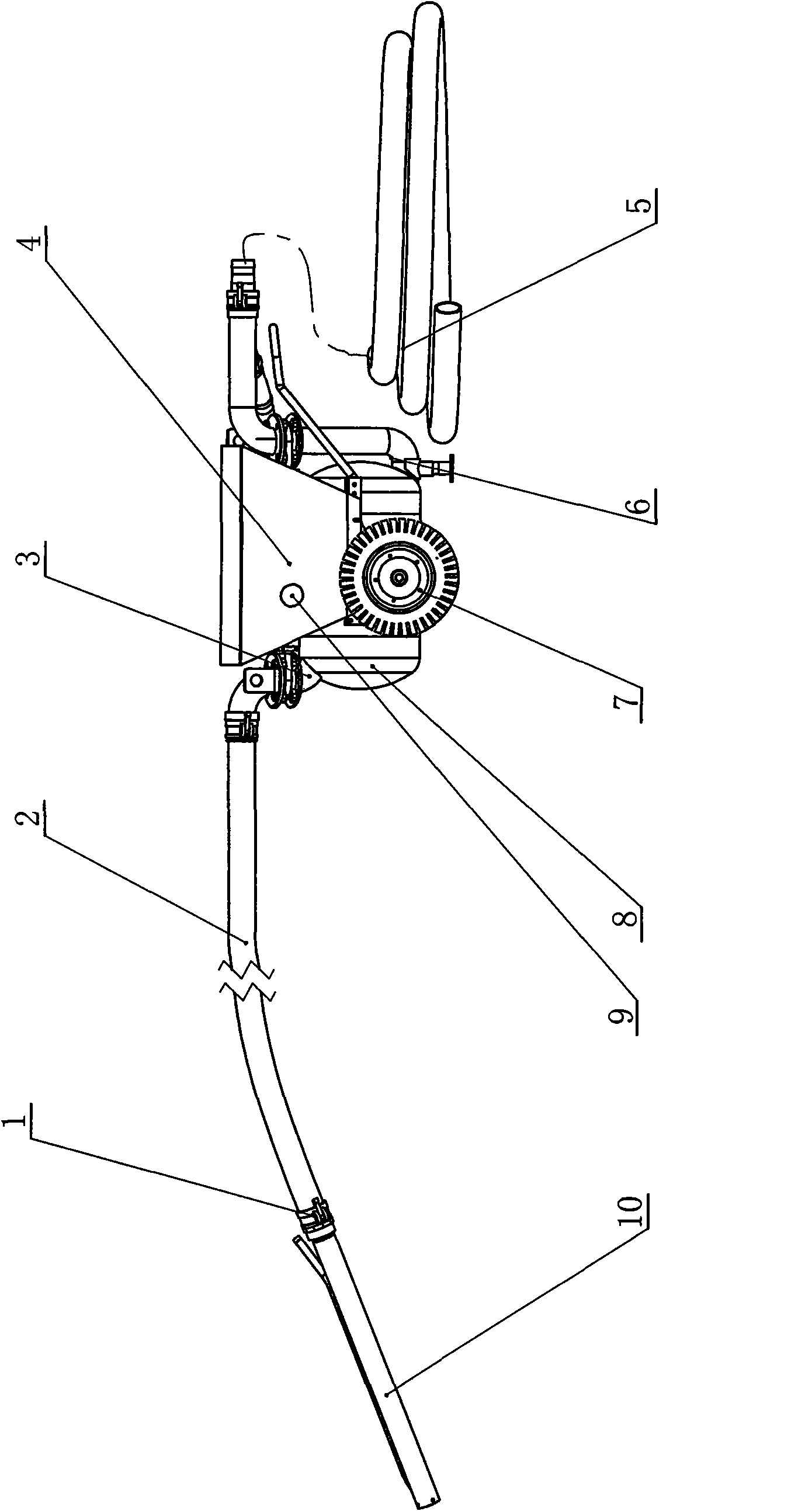
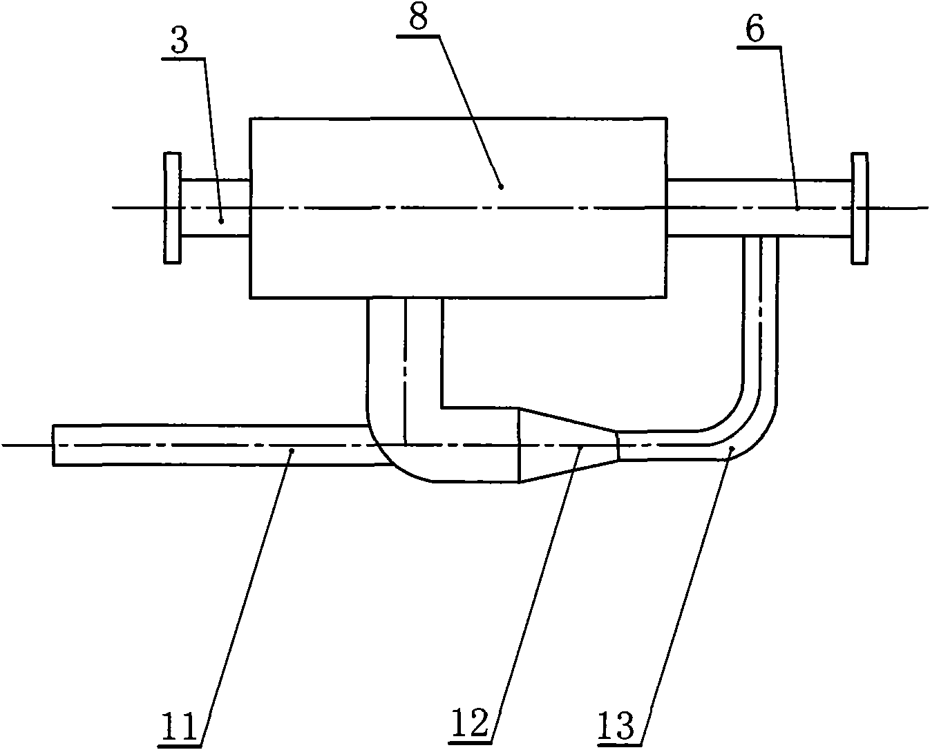
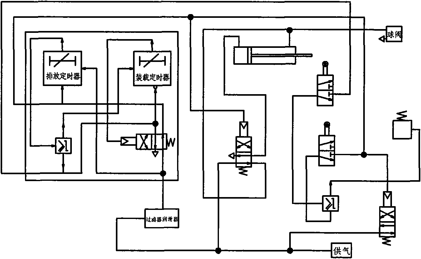
[0012] A material transfer pump, such as figure 1 , 2 , 3, including the storage tank 8, the upper part of the left part of the storage tank 8 is provided with a feed port 3, the feed port 3 is sealed and connected with the feed pipe 2, and the feed port 3 is equipped with a feed knife Valve, the other end of the feeding pipe 2 is connected with a suction pipe 10, the lower part of the right part of the storage tank 8 is provided with a discharge port 6, a discharge gate knife valve is installed at the discharge port 6, and the discharge port 6 is sealed and connected There is a discharge pipe 5, the feed pipe 2 and the discharge pipe 5 communicate with the storage tank 8 respectively, the storage tank 8 is connected with the control system 4, the storage tank 8 is provided with a high-pressure air inlet 9, and the high-pressure air The air in...
PUM
 Abstract
Description
Claims
Application Information