Friction welding apparatus

Inactive Publication Date: 2013-11-12
TOYOTA IND CORP +1
View PDF17 Cites 3 Cited by
  • Summary
  • Abstract
  • Description
  • Claims
  • Application Information

AI Technical Summary

Benefits of technology

[0009]According to this construction, it is possible to engage the two clutches with each other such that the RPM of the spindle is a low speed RPM (e.g., 150 rpm), and that the phase of the spindle side clutch and the phase of the mating clutch coincide with each other. As a result, there is no fear of breakage of the engagement portions or generation of large impulsive noise as in the prior-art technique of Patent Document 1. Further, when the clutches are thus engaged with each other, the rotation

Problems solved by technology

However, in Patent Document 1, the rotation frequency at which the engagement of both clutches is effected is, for example, 300 rpm, so that when both clutches are engaged with each other, the engagement portions may suffer breakage.
Further, this engagement involves generation of large impulsive noise.
In this case, the phase precision in the bonding of both workpieces is unsatisfactory.
In this way,

Method used


Image

  • Friction welding apparatus
  • Friction welding apparatus
  • Friction welding apparatus

Examples


Embodiment Construction

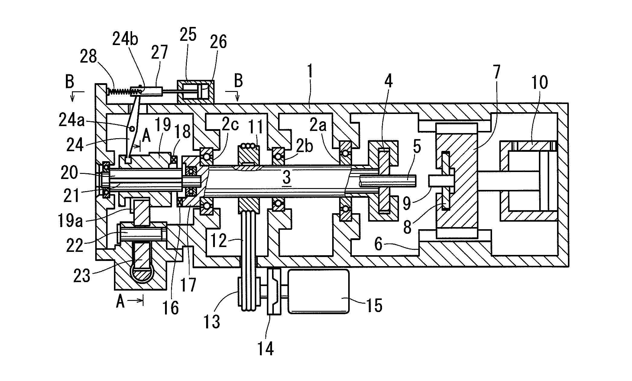
[0017]In the following, a best mode for carrying out the present invention will be described with reference to the drawings. As shown in FIG. 1, one workpiece 5 is grasped by a chuck 4 on a spindle 3 so as to be coaxial with the spindle 3 which is rotatably supported by a casing 1 via bearings 2a, 2b, and 2c. The one workpiece 5 is brought into frictional contact with another workpiece 9 grasped by a chuck 8 via a table 7 so as to be slidable in the axial direction of the spindle 3 on a sliding member 6 that is integral with the casing 1.

[0018]For this purpose, the table 7 can be moved toward and away from the spindle 3 by a hydraulic device 10 and can cause pressurization on the spindle 3. The spindle 3 is rotated by a servo motor 15 via a pulley 11, a belt 12, a pulley 13, and an electromagnetic clutch 14.

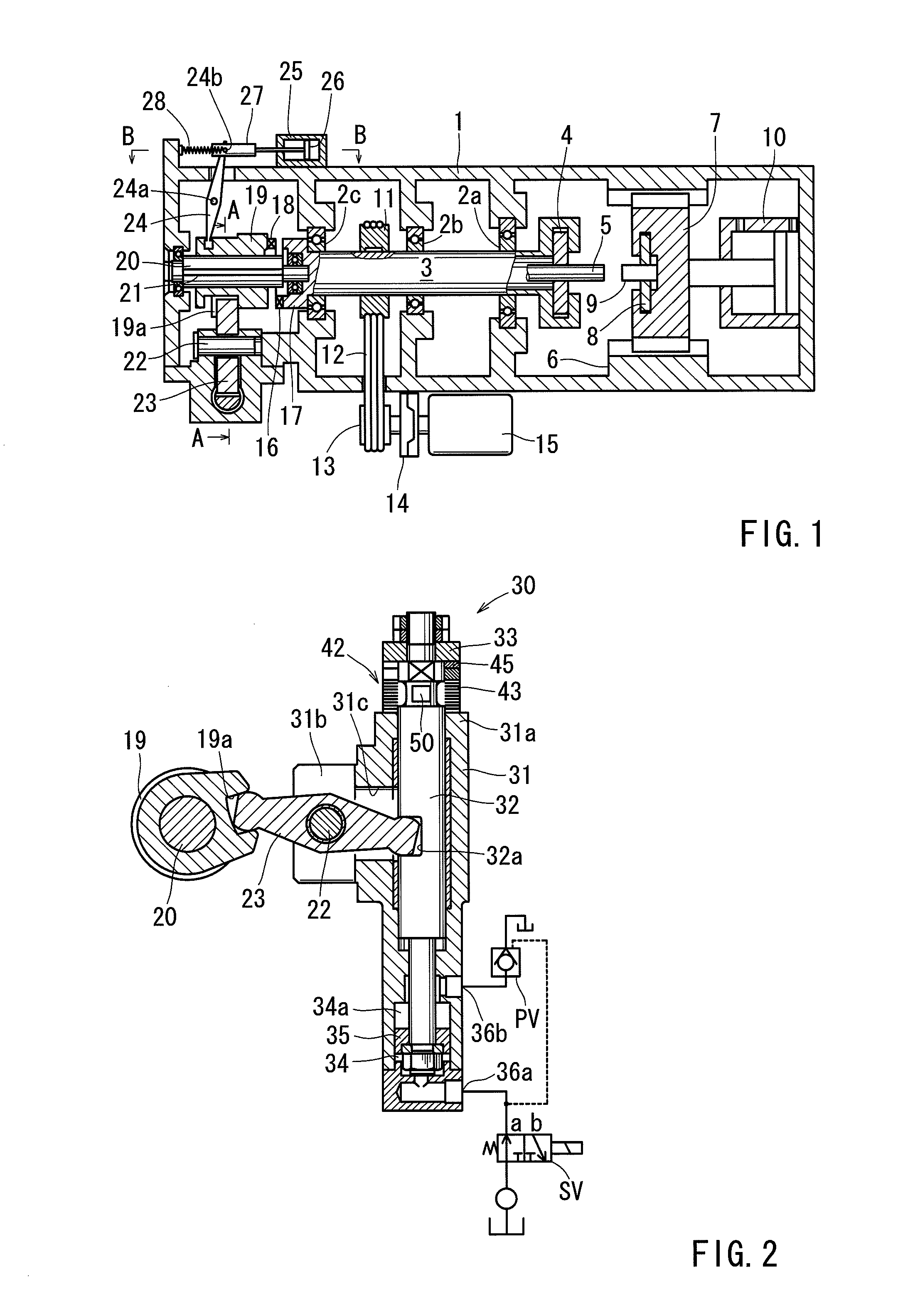
[0019]On the side of the spindle 3 opposite to the chuck 4, there is provided a cam clutch 17 having a claw 16 integral therewith; on a side opposite thereto, a cam clutch 19 hav...


PUM


Abstract

Disclosed is a friction welding apparatus in which electricity is supplied to a servo motor to rotate a spindle to thereby impart a fixed relative rotational motion to one workpiece and another workpiece, and, while doing so, the one workpiece and the other workpiece are brought into contact with each other and imparted a frictional thrust thereto to soften a bonding interface between the two workpieces. After this, the friction welding apparatus undergoes speed reduction until the RPM of the spindle becomes a phase adjustment RPM; when the RPM of the spindle attains the phase adjustment RPM, a clutch device is engaged with the spindle, and the electricity supply to the servo motor is cut off to stop the rotation of the spindle.

Description

TECHNICAL FIELD[0001]The present invention relates to a friction welding apparatus for bonding workpieces to each other by utilizing frictional heat.BACKGROUND ART[0002]Known examples of a friction welding apparatus of this type are disclosed in Patent Documents 1 and 2. Patent Document 1 discloses a technique in which a stopping device is operated through clutch engagement to perform phase adjustment on both workpieces. Patent Document 2 discloses a technique in which phase adjustment is performed on both workpieces through torque control and rotation frequency control of a servo motor.[0003]Patent Document 1: JP 3-184680 A[0004]Patent Document 2: JP 2000-84680 A[0005]However, in Patent Document 1, the rotation frequency at which the engagement of both clutches is effected is, for example, 300 rpm, so that when both clutches are engaged with each other, the engagement portions may suffer breakage. Further, this engagement involves generation of large impulsive noise. For example, w...

Claims


Application Information

Patent Timeline
IPC IPC(8): B32B37/00
CPCB23K20/12B23K20/121B23K2201/06B23K2101/06
Inventor KAWAURA, KOICHIKURAYA, YASUMASAMIYAJI, SATORU
Owner TOYOTA IND CORP
Why Eureka
Try Eureka