Emergency Lighting with Charging Indicator Circuitry

a technology of emergency lighting and indicator circuits, applied in circuit arrangements, emergency power supply arrangements, transportation and packaging, etc., can solve the problems of increased labor intensity, increased cost, and reduced productivity, so as to improve efficiency, speed up production, and simplify the whole circuit design

Active Publication Date: 2013-07-25
HESHAN BEISHI SCI & TECH CO LTD
View PDF17 Cites 10 Cited by
  • Summary
  • Abstract
  • Description
  • Claims
  • Application Information

AI Technical Summary

Benefits of technology

[0012]Further, the emergency switch circuit is connected with the ground, the power source module, and the negative electrode of the light-emitting unit respectively. The intelligent emergency switch is connected with the ground and the power source module. When the utility power is supplied normally, the intelligent emergency switch outputs voltage to the negative electrode of the light-emitting unit; when the utility power is interrupted or the test switch is pressed, the intelligent emergency circuit connects the negative electrode of the light-emitting unit and the electric wires, the electric energy of the battery module is led to the ground through the light-emitting unit and the intelligent emergency switch, thus the light-emitting unit is lighted. By means of the way for controlling, lighting and extinguishing the light-emitting unit, not only a simpler design for the whole circuit can be obtained, but also any complex IC module is not needed, the cost is further reduced, the production is sped up, and the economic efficiency is raised.
[0013]Further, the power source module includes a rectifier module for rectifying the utility power, and a voltage-stabilizing module for stabilizing the output voltage. The current and voltage of the battery module should be controlled properly so as to prevent the failures of the battery module due to a large current. In order to maintain the safety of the charging indicator circuitry and the battery module, the charging indicator circuitry is provided with the voltage-drop circuit, as well as the voltage at the joint point of the battery module and the power source module should be relatively stable, thus the voltage may be stabilized within a range suitable for charging by the rectifier module and the voltage-stabilizing module

Problems solved by technology

Although some products have the function of charging indication, their circuitry is complicated and a comparator or a complicated IC-chip is needed to complete the

Method used


Image

  • Emergency Lighting with Charging Indicator Circuitry
  • Emergency Lighting with Charging Indicator Circuitry
  • Emergency Lighting with Charging Indicator Circuitry

Examples


Embodiment Construction

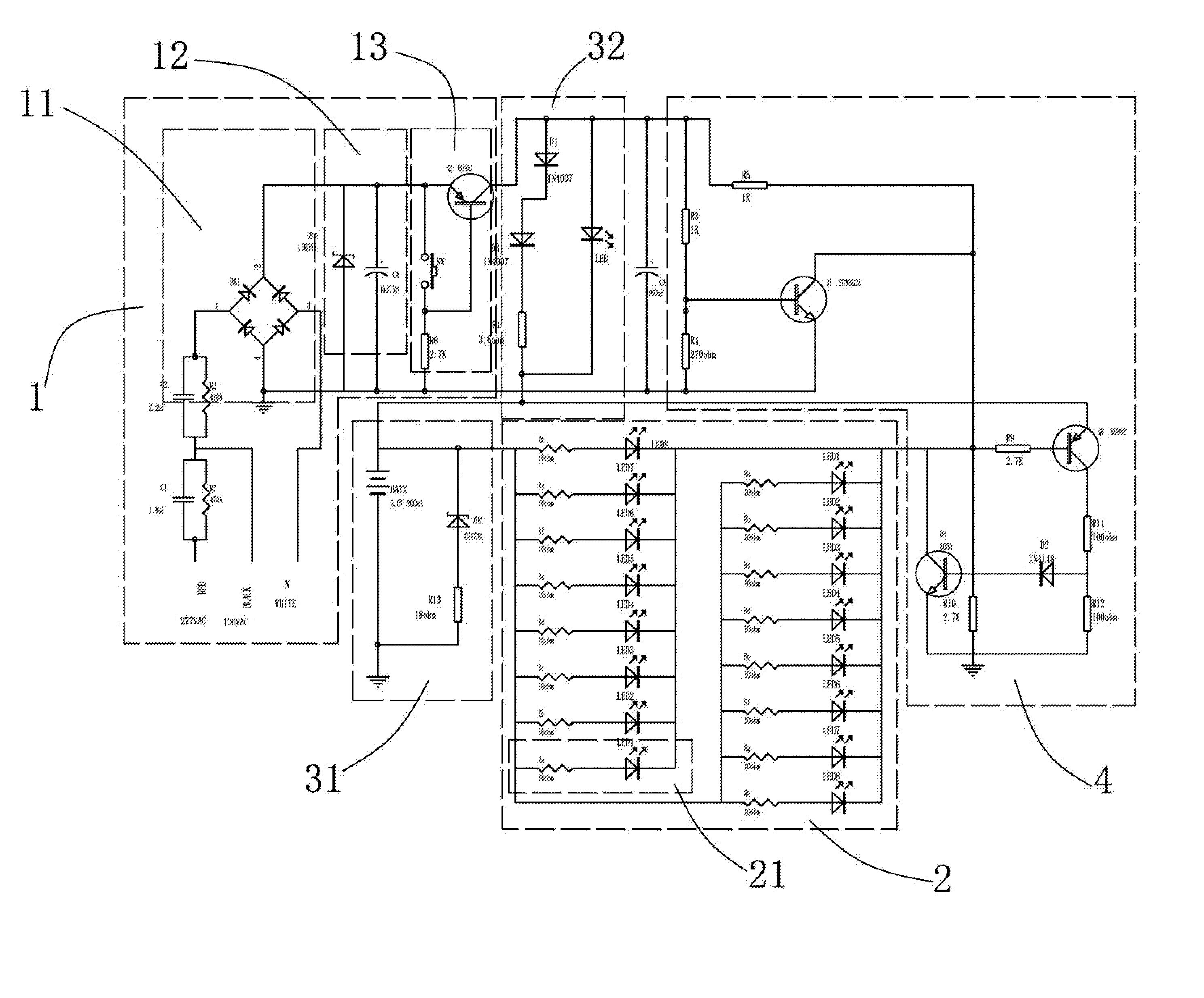
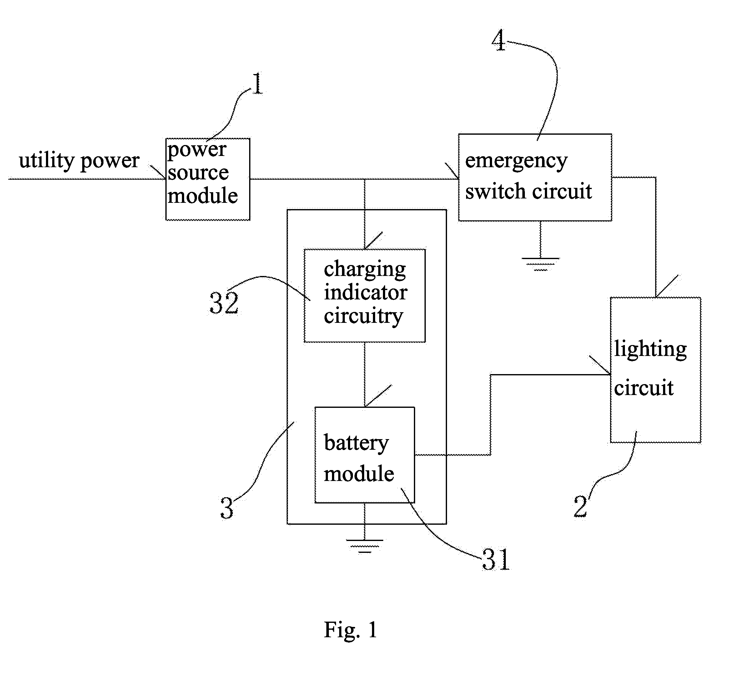
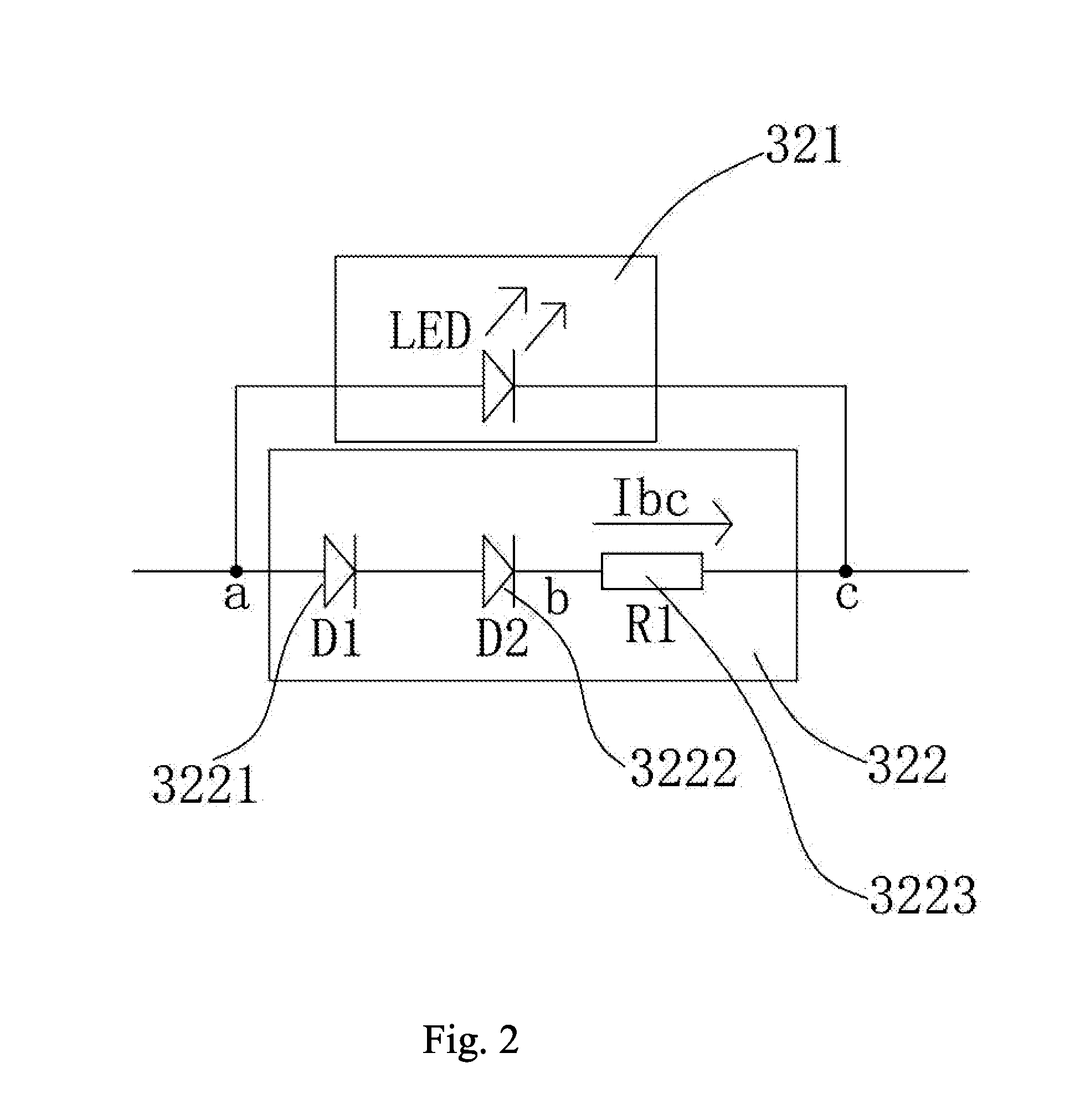
[0024]Referring to FIG. 1 to FIG. 3, an emergency lighting with a charging indicator circuitry according to an embodiment of the invention includes a power source module 1, a lighting circuit 2, a battery circuit 3, and an emergency switch circuit 4. The battery circuit 3 includes a charging indicator circuitry 32 for indicating the charging status of a battery and a battery module 31 for storing the electric energy and discharging the electric power when needed. Via the charging indicator circuitry 32, the power source module 1 is connected with the battery module 31 which its power output terminal is connected to the lighting circuit 2. And the power source module 1 is connected with the lighting circuit 2 via the emergency switch circuit 4. The power source module 1 is connected with the battery module 31 via the charging indicator circuitry 32, so that the charging indicator circuitry 32 indicates that charging is on going, when the power is supplied normally, since the charging...


PUM


Abstract

Emergency lighting with a charging indicator circuitry comprises a power source module, a lighting circuit, a battery circuit, and an emergency switch circuit. The battery circuit includes charging indicator circuitry and a battery module; the power source module is connected with the battery module via the charging indicator circuitry. When the utility power is interrupted or a test switch is pressed, the light of the charging indicator circuitry goes out to indicate that the emergency lighting is in discharging status. When the utility power is supplied normally, if a battery within the battery module is in disconnected state, the light of the indicating circuitry goes out to indicate that the emergency lighting is in disconnected state. The charging indicator circuitry may be a simple light-emitting indicating circuit, has no need for much modification to the original circuit during manufacture and design, and may be simple and quickly-responsive.

Description

SUMMARY OF THE INVENTION[0001]The present invention relates to an emergency lighting, and more particularly, to an emergency lighting with a charging indicator circuitry.[0002]For emergency lighting on the current market, most products have only one LED indicator which is used only to indicate whether commercial power is supplied or not, and the LED indicator is still “ON” after the test switch is pressed or the battery is disconnected. The LED indicator cannot indicate the charging status of the battery and cannot play the role of a charging indicator. Although some products have the function of charging indication, their circuitry is complicated and a comparator or a complicated IC-chip is needed to complete the action of charging indication. As a result, the difficulty in the research and development is greatly increased, the productivity is reduced, and the cost is raised.[0003]In order to solve the above-mentioned problems, it is an object of the present invention to provide em...

Claims


Application Information

Patent Timeline
IPC IPC(8): H02J9/00H05B44/00
CPCH02J9/065H05B33/0842H05B33/0812Y02B20/343H05B45/395H05B45/00Y02B20/30
Inventor HUANG, ALEXCHEN, QIUSHENG
Owner HESHAN BEISHI SCI & TECH CO LTD
Why Eureka
Try Eureka