Method and system for interactive simulation of materials and models

a simulation method and material technology, applied in the field of computer simulations, can solve the problems of -body simulation, difficulty in simulating rigid or semi-rigid objects, and inability to simulate soft objects

Active Publication Date: 2013-07-25
MILLMAN ALAN
View PDF0 Cites 46 Cited by
  • Summary
  • Abstract
  • Description
  • Claims
  • Application Information

AI Technical Summary

Benefits of technology

[0044]In accordance with preferred embodiments of the present invention, some of the problems associated with sim...

Problems solved by technology

A limitation of rigid-body simulations is that they do not allow the simulation of soft objects.
A limitation of flexible-body simulations is that they have difficulty simulating rigid or semi-rigid objects.
As springs are made stiffer, instabilities arise, and their equations become increasingly difficult to solve at interactive frame-rates.
Another limitation of flexible-body simulations is that they simulate rotations by propagating translations across a network of springs.
A limitation of FEA simulations is that they do not allow interaction with simulated objects, due to the time required for computation.
Another limitation of FEA is the requirement that FEM objects be composed of homogeneously-shaped elements, which makes their creation more difficult, error-prone, and in certain situations, impossible.
One limitation of some of these technologies is the necessity to precompute certain aspects of the model's response to forces, or to make certain variables unchangeable.
This makes it difficult to generate objects, or to change the characteristics of existing objects, while the simulation is running.
Another limitation of certain newer interactive soft-body simulation technologies is their inability to simulate materials that r...

Method used


Image

  • Method and system for interactive simulation of materials and models
  • Method and system for interactive simulation of materials and models
  • Method and system for interactive simulation of materials and models

Examples


Embodiment Construction

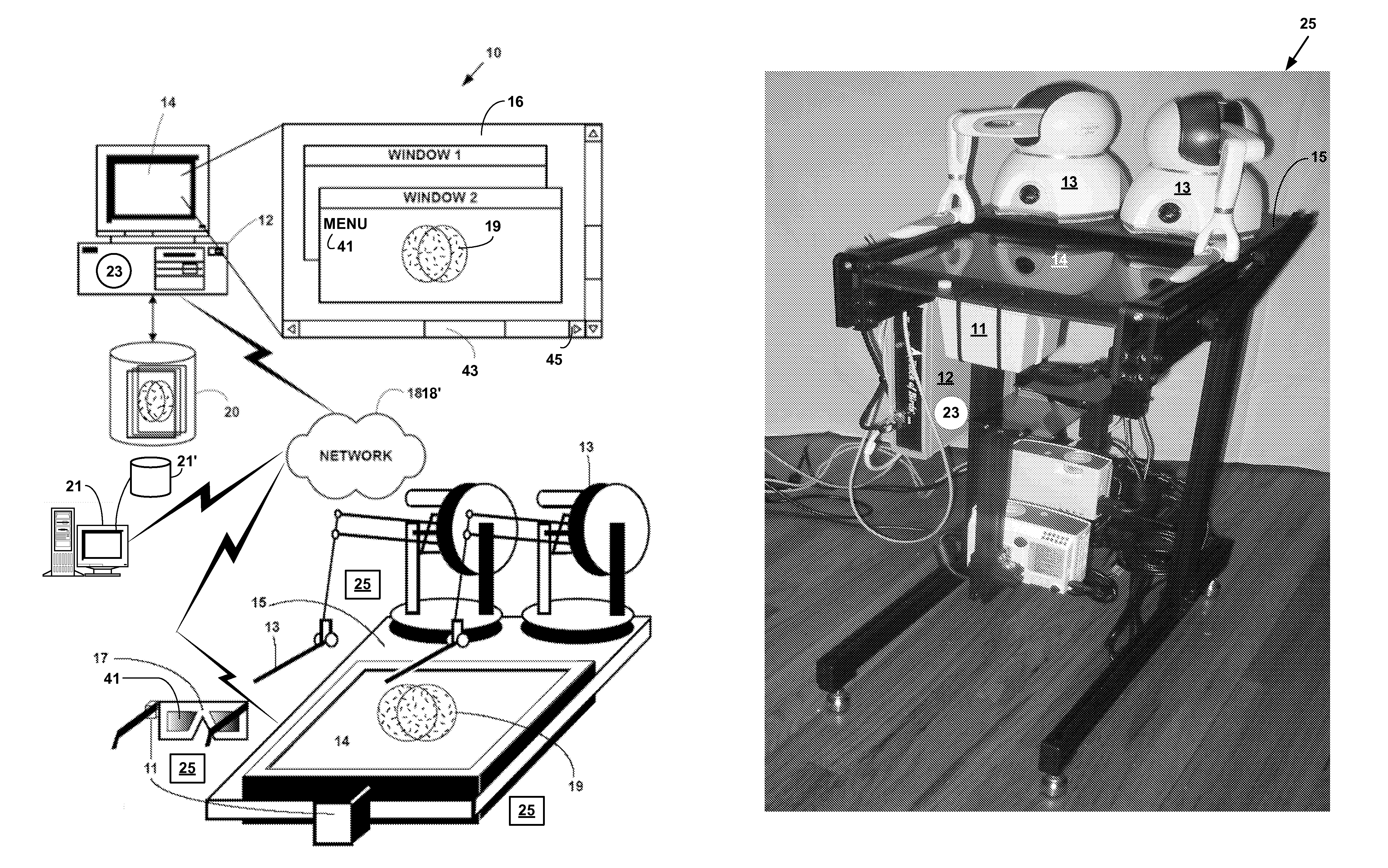
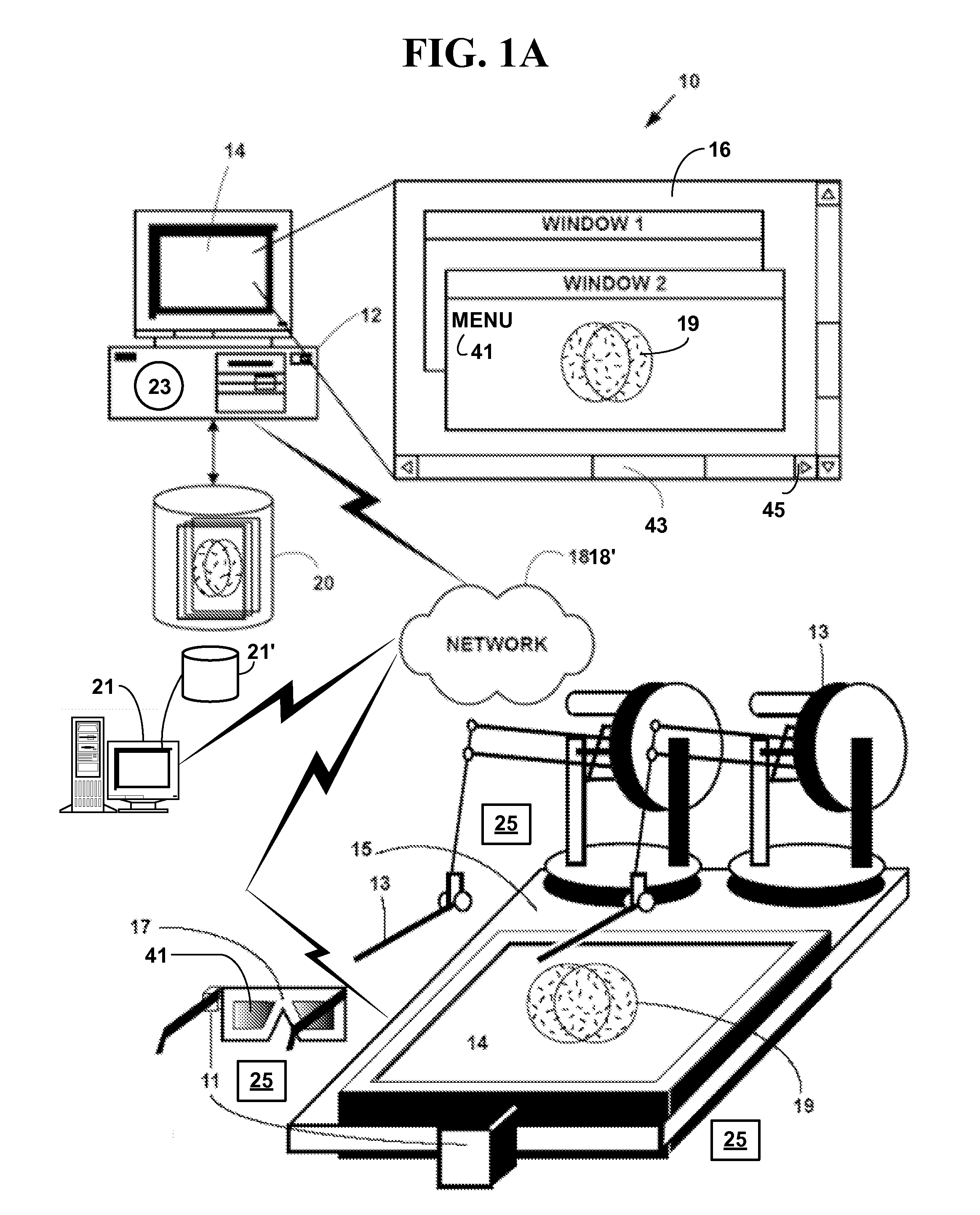
[0068]FIG. 1A is a block diagram illustrating an exemplary simulation system 10. The exemplary system 10 includes one or more network devices 12 each with one or more processors or central processing units (CPUs), an application 23 and one or more displays 14 (two of which are illustrated). The display 14 may include any of a windowed graphical user interface (“GUI”) 16 with multiple windows, or one or more simulation views 19, to a user. One or more databases 20 (one of which is illustrated) include data in various digital data formats. The databases 20 may be integral to a memory system on the network device 12 or in secondary storage such as a hard disk, floppy disk, optical disk, or other non-volatile mass storage devices. The network device 12 and the databases 20 may be in communications with and accessible via one or more communications networks 18 including a cloud communications network 18′ (FIG. 15).

[0069]The network devices 12 are in communications with a cloud communicat...


PUM


Abstract

A method and system for drawing, displaying, editing animating, simulating and interacting with one or more virtual polygonal, spline, volumetric models, three-dimensional visual models or robotic models. The method and system provide flexible simulation, the ability to combine rigid and flexible simulation on plural portions of a model, rendering of haptic forces and force-feedback to a user.

Description

CROSS REFERENCES TO RELATED APPLICATIONS[0001]This application claims priority to U.S. Utility patent application Ser. No. 11 / 784,455, filed Apr. 6, 2007, which claims priority to U.S. Provisional Patent Application 60 / 790,093, filed Apr. 8, 2006, U.S. Utility patent application Ser. No. 11 / 784,455, issued as U.S. Pat. No. 8,395,626, on Mar. 12, 2013, the contents of which are incorporated by reference.FIELD OF THE INVENTION[0002]This invention relates to computer simulations. More specifically, it relates to a method and system for simulation of materials and models with combined rigid and flexible components, and a method of aligning hardware components for interacting with virtual objects.BACKGROUND OF THE INVENTION[0003]Simulation has many applications. It is used to design and prototype products. It is used to engineer and test materials and designs. It is used for training and education. It is used to create content for various forms of entertainment, animation, and virtual re...

Claims


Application Information

Patent Timeline
IPC IPC(8): G06T13/20
CPCG06T13/20G06F17/5009G06T19/00G06F2217/16G06F17/5018G06F2111/10G06F30/23G06F30/20G06F30/25G06F2119/14
Inventor MILLMAN, ALAN
Owner MILLMAN ALAN
Why Eureka
Try Eureka