Active illumination scanning imager

a scanning imager and active illumination technology, applied in the field of active illumination scanning imagers, can solve problems such as beam defocusing, and achieve the effect of facilitating the collimation of light beams

Inactive Publication Date: 2013-07-25
IEE INT ELECTRONICS & ENG SA
View PDF16 Cites 39 Cited by
  • Summary
  • Abstract
  • Description
  • Claims
  • Application Information

AI Technical Summary

Benefits of technology

[0008]The invention facilitates collimation of a ligh...

Problems solved by technology

Due to system ageing, misalignment of the opt...

Method used


Image

  • Active illumination scanning imager
  • Active illumination scanning imager
  • Active illumination scanning imager

Examples


Embodiment Construction

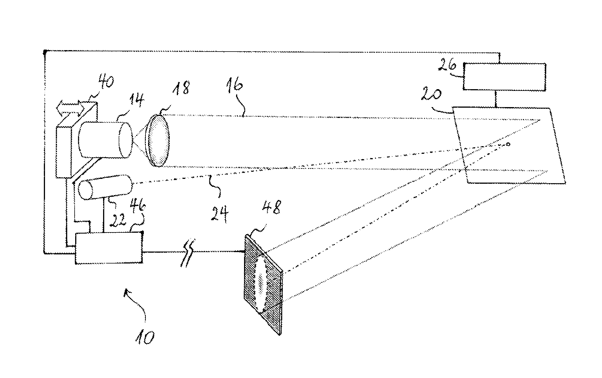
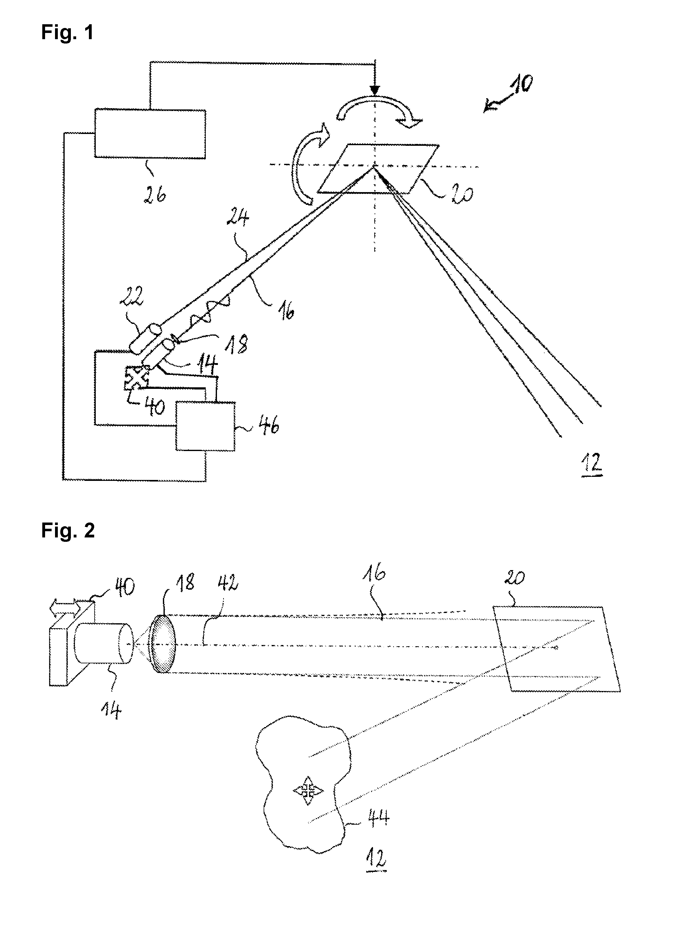
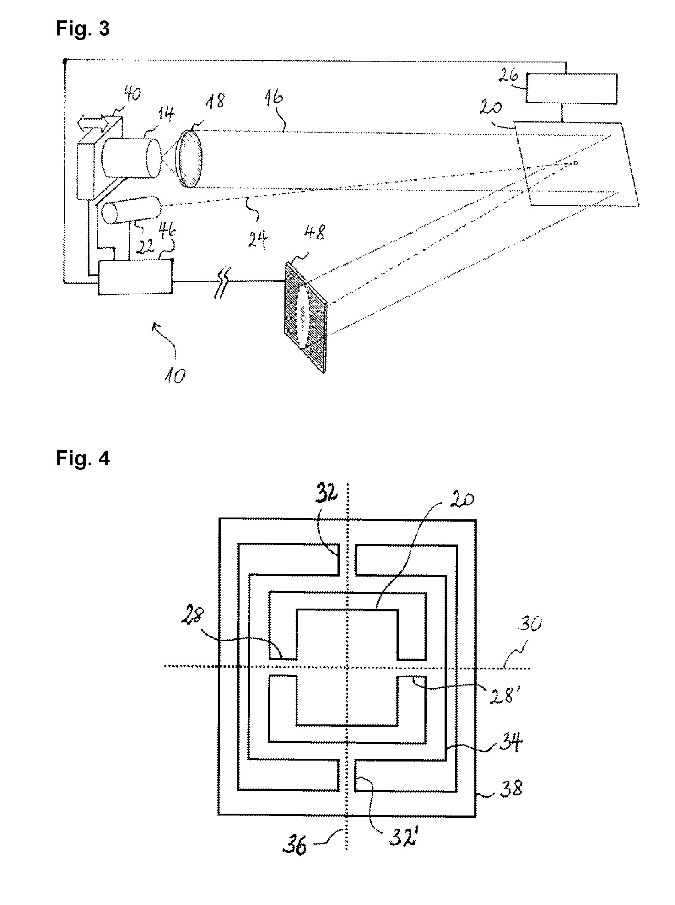
[0027]FIG. 1 schematically shows an active-illumination scanning imager 10 according to a preferred embodiment of the invention. The active-illumination scanning imager 10 is configured for producing a range image of the scene 12 under observation. It comprises a laser diode 14 for producing a pulsed laser beam 16, an optical collimator 18 (here a collimating lens) for collimating the laser beam 16, a scanning mirror 20 for scanning the laser beam 16 through the scene 12, and a photodetector 22 (e.g. a single photon avalanche diode) for detecting a fraction of the light 24 that is reflected from the scene 12, via the scanning mirror 20. The photodetector 24 is equipped with a time-to-digital converter (TDC, not shown) that measures the duration between a reference point in time (the time of emission of a laser pulse) and the instant when the return pulse from the scene 12 hits the photodetector 24. The time interval between emission and reception of the laser pulse corresponds to tw...


PUM


Abstract

An active-illumination scanning imager (10) comprises a light source (14) for producing a light beam (16), an optical collimator (18) for collimating the light beam, a scanning mirror (20) for scanning the light beam through a scene (12) to be imaged, and a light detector (22) arranged with respect to the scanning mirror in such a way as to receive a fraction (24) of said light beam reflected from said scene, via the scanning mirror. The imager further includes an actuator (40) configured to position the light source and/or the optical collimator relative to each other and/or the light detector relative to the scanning mirror, and a controller (46) operatively connected to the actuator for controlling the positioning.

Description

TECHNICAL FIELD[0001]The present invention generally relates to an active-illumination scanning imager, i.e. a scanning imager that illuminates the scene to be imaged, in particular such an scanning imager that comprises an oscillating scanning mirror to scan a light beam though the scene to be imaged.BACKGROUND ART[0002]EP 1 289 273 discloses a scanning camera equipped with a micromechanical mirror that oscillates about two mutually perpendicular axes to scan an object. The scene is imaged in time-division multiplexed manner onto a punctiform optoelectronic sensor. The scanning camera, however, does not illuminate the scene actively.[0003]Imagers with active scene illumination are used, for instance, for recording range images based on the time-of-flight measurement principle. In the context of the present document, a “range image” is an image composed of pixels, each of which contains a distance value representing the distance from the imager to the point in the scene with which t...

Claims


Application Information

Patent Timeline
IPC IPC(8): G01B11/24G01S17/89
CPCG01S7/4814G01S7/4817G01B11/24G02B26/0833G02B26/127G01S17/89
Inventor DECOSTER, YVES
Owner IEE INT ELECTRONICS & ENG SA
Why Eureka
Try Eureka