Lighting device, display device and television receiver
a technology of display device and light source, which is applied in the field of light source device, display device, and television receiver, can solve the problems of increased cost, increased brightness, and light leakage through, and achieve the effect of suppressing even brightness and low cos
- Summary
- Abstract
- Description
- Claims
- Application Information
AI Technical Summary
Benefits of technology
Problems solved by technology
Method used
Image

Examples
first embodiment
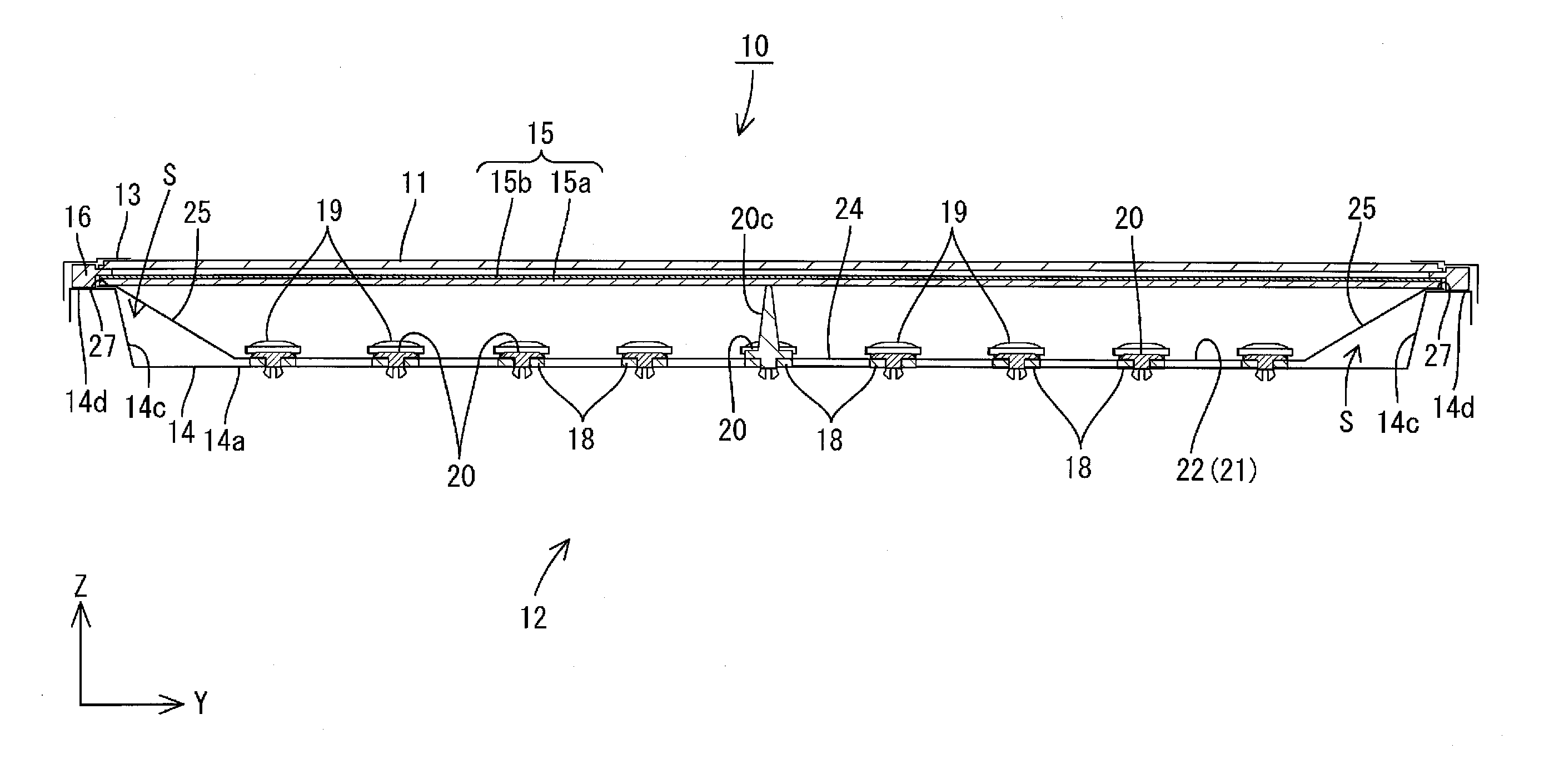
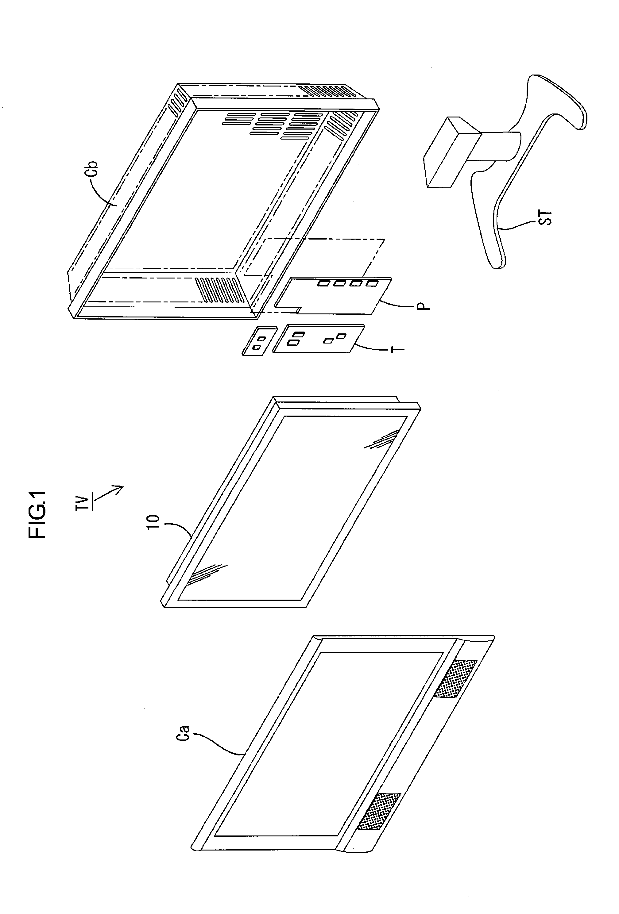
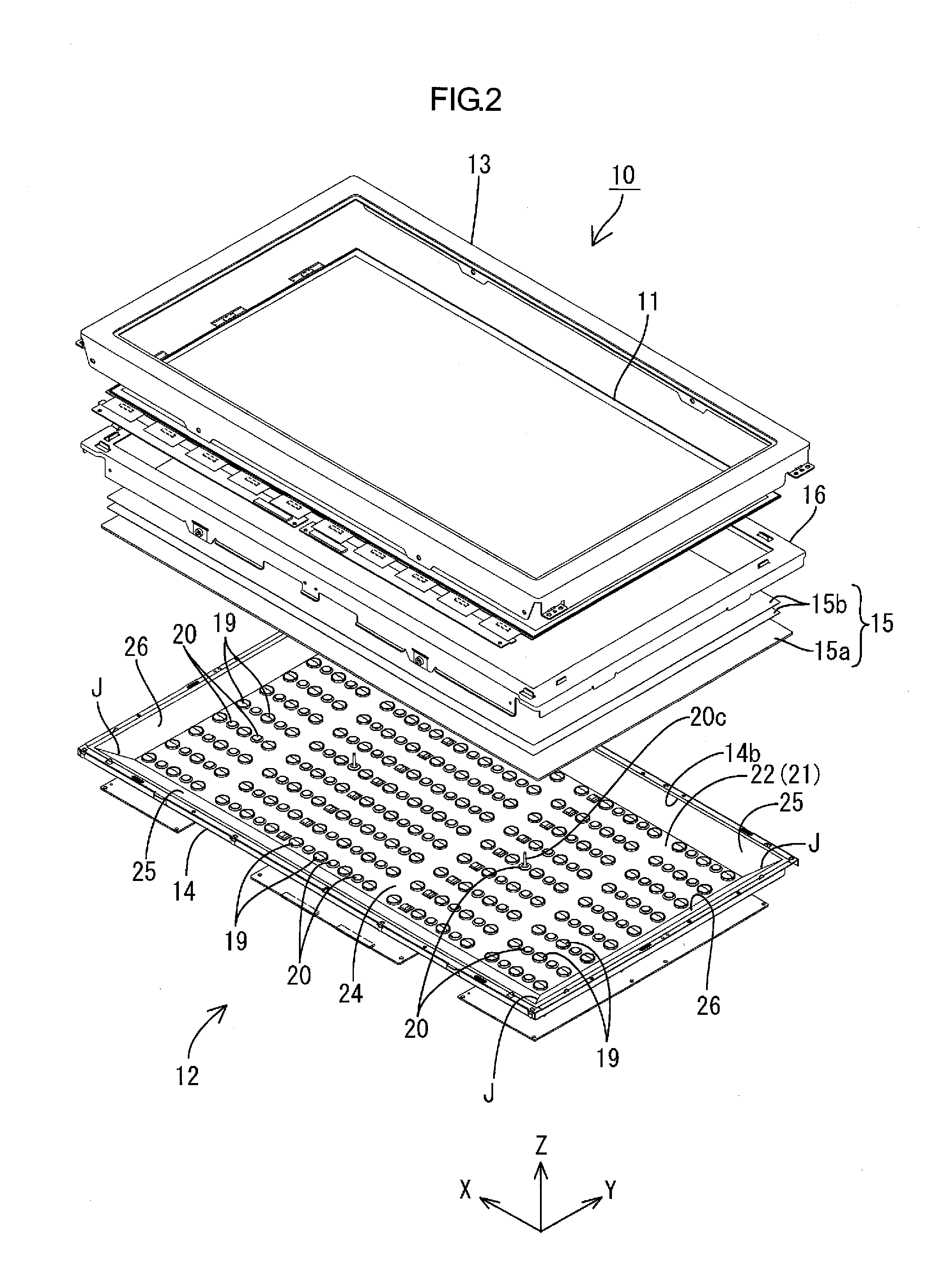
[0070]A first embodiment of the present invention will be described with reference to FIGS. 1 to 15. According to the present embodiment, a liquid crystal display device 10 will be described byway of example. In parts of the drawings, an X-axis, a Y-axis, and a Z-axis are drawn, and the directions of the respective axes correspond to the directions illustrated in the drawings. An upper side and a lower side of FIGS. 3 and 4 correspond to a front side and a back side, respectively.
[0071]As illustrated in FIG. 1, a television receiver TV according to the present embodiment includes the liquid crystal display device 10, front and rear cabinets Ca and Cb sandwiching and housing the liquid crystal display device 10 therebetween, a power supply P, a tuner T, and a stand ST. The liquid crystal display device (display device) 10 has a horizontally long (elongated) square (rectangular or oblong) shape as a whole, and is housed in a vertically disposed manner. As illustrated in FIG. 2, the li...
second embodiment
[0140]A second embodiment of the present invention will be described with reference to FIGS. 29 to 33. The second embodiment differs from the first embodiment in that the light source is changed to a hot cathode tube 30 and that a diffuser plate 115a has a modified configuration. Redundant description of structures, operation, or effects similar to those of the first embodiment will be omitted.
[0141]As illustrated in FIGS. 29 and 30, a backlight unit 112 according to the present embodiment includes a single hot cathode tube 30 as the light source. The hot cathode tube 30 has a tubular shape (linear shape) as a whole and includes a hollow glass tube and a pair of electrodes disposed at the end portions of the glass tube. The glass tubes may enclose mercury and a rare gas, and the internal wall surfaces of the glass tubes may be coated with a fluorescent material. The hot cathode tube 30 has a light emitting surface corresponding to an outer peripheral surface of the glass tube. Thus,...
third embodiment
[0152]A third embodiment of the present invention will be described with reference to FIG. 34. In the third embodiment, the light source of the second embodiment is changed to cold cathode tubes 40. Redundant description of structures, operation, or effects similar to those of the first embodiment will be omitted.
[0153]In accordance with the present embodiment, the cold cathode tubes 40 as the light source have a long tubular (linear) shape, as illustrated in FIG. 34. Specifically, the cold cathode tubes 40 include a hollow and long glass tube whose end portions are sealed, and a pair of electrodes enclosed in the glass tube at the ends. The glass tubes may contain mercury, a rare gas and the like, and the inner wall surfaces thereof are coated with a fluorescent material. At the end portions of the cold cathode tubes 40, relay connectors (not illustrated) are disposed and connected to lead terminals protruding from the electrodes to the outside of the glass tubes. The cold cathode ...
PUM
| Property | Measurement | Unit |
|---|---|---|
| light reflectance | aaaaa | aaaaa |
| light reflectance | aaaaa | aaaaa |
| light reflectance | aaaaa | aaaaa |
Abstract
Description
Claims
Application Information
 - R&D
- Intellectual Property
- Life Sciences
- Materials
- Tech Scout
- Unparalleled Data Quality
- Higher Quality Content
- 60% Fewer Hallucinations
Browse by: Latest US Patents, China's latest patents, Technical Efficacy Thesaurus, Application Domain, Technology Topic, Popular Technical Reports.
© 2025 PatSnap. All rights reserved.Legal|Privacy policy|Modern Slavery Act Transparency Statement|Sitemap|About US| Contact US: help@patsnap.com