Photocatalyst unit

Inactive Publication Date: 2013-07-25
SMARTECH
View PDF2 Cites 5 Cited by
  • Summary
  • Abstract
  • Description
  • Claims
  • Application Information

AI Technical Summary

Benefits of technology

[0016]According to the present invention, the following effects may be obtained.
[0017]Firstly, the ultraviolet radiation can be stereoscopically irradiated all over the photocatalyst member and the photocatalyst filters such that irradiation efficiency of the light beam can be increased and a photocatalytic reaction area can be increased.
[0018]Also, the ultraviolet radiation from the ultraviolet radiation can uniformly reach the photocatalyst.
[0019]Also, the photocatalyst member can be formed parallel to the flow direction of air

Problems solved by technology

However, when the ultraviolet radiation is irradiated on photocatalyst bodies, the ultraviolet radiation is blocked by a front photocatalyst body not to reach the remaining rear portions.
On the contrary, if the contact area is increased, air flow paths become narrow, thereby increasing the pressure loss.
In addition, for a structure like a honeycomb, a photocatalytic action is acti

Method used


Image

  • Photocatalyst unit
  • Photocatalyst unit
  • Photocatalyst unit

Examples


Example

BEST MODE

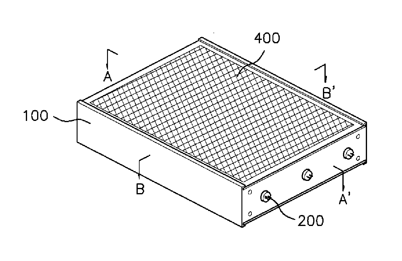
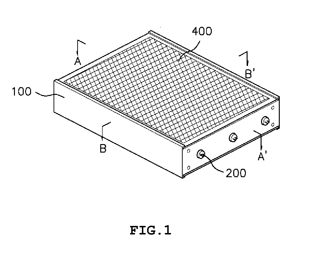
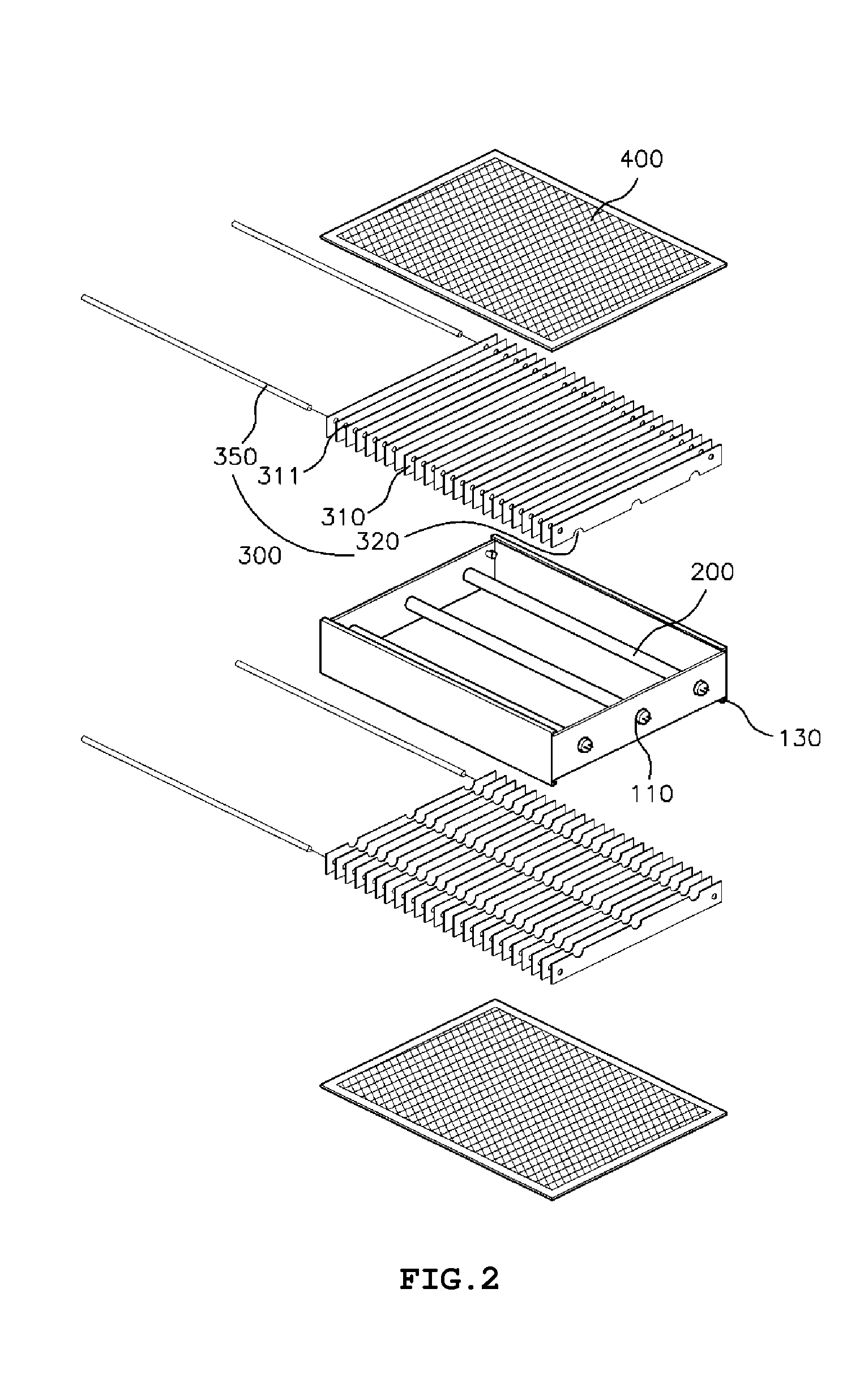
[0026]According to an exemplary embodiment of the present invention, there is provided a photocatalyst unit, including a body made of a plate with openings at upper and lower sides thereof and having one or more pairs of opposing lamp fixing means provided therein; ultraviolet radiation lamps each coupled to the lamp fixing means; a photocatalyst member coupled to the body and having a surface coated with a photocatalyst, wherein the photocatalyst member includes a plurality of plates disposed orthogonally to the ultraviolet radiation lamps, wherein the plates are disposed parallel to a flow direction of air and spaced to each other in order to form gaps between adjacent plates; and photocatalyst filters each disposed on upper and lower sides of the photocatalyst member and mounted on the body to cover upper and lower sides of the body, wherein the photocatalyst filters are applied with a photocatalyst.

Exemplary Embodiments

[0027]Exemplary embodiments of the present inventio...


PUM


Abstract

The present invention relates to a photocatalyst unit. More particularly, the photocatalyst unit includes a body made of a plate with openings at upper and lower sides thereof and having one or more pairs of opposing lamp fixing means provided therein; ultraviolet radiation lamps each coupled to the lamp fixing means; a photocatalyst member coupled to the body and having a surface coated with a photocatalyst, wherein the photocatalyst member includes a plurality of plates disposed orthogonally to the ultraviolet radiation lamps, wherein the plates are disposed parallel to a flow direction of air and spaced to each other in order to form gaps between adjacent plates; and photocatalyst filters each disposed on upper and lower sides of the photocatalyst member and mounted on the body to cover upper and lower sides of the body, wherein the photocatalyst filters are applied with a photocatalyst.

Description

TECHNICAL FIELD[0001]The present invention relates, in general, to a photocatalyst unit, and more particularly to a photocatalyst unit in which ultraviolet radiation emitted from an ultraviolet radiation lamp is maximizedly irradiated on the surrounding photocatalyst members and photocatalyst filters to increase an ultraviolet radiation reaction area.BACKGROUND ART[0002]Typically, a photochemical reaction caused by a combination of a photocatalyst and ultraviolet radiation provides excellent sterilizing and deodorizing actions, and thus is used for air cleaning and sterilizing. In particular, the photocatalyst is a useful technology in that the photocatalyst can be semipermanently used, be harmless to humans to be stably employed, and don't cause a secondary contaminant in contrast to other contamination prevention technologies.[0003]However, when the ultraviolet radiation is irradiated on photocatalyst bodies, the ultraviolet radiation is blocked by a front photocatalyst body not t...

Claims


Application Information

Patent Timeline
IPC IPC(8): A61L9/20
CPCF24F2003/1667A61L9/205F24F8/22A61L9/20F24F8/167
Inventor JEONG, CHEOLGYU
Owner SMARTECH
Why Eureka
Try Eureka