
Lane departure control system

a control system and lane departure technology, applied in the direction of steering initiation, instruments, vessel construction, etc., can solve the problems of uncomfortable ride for the occupants of the vehicle, and achieve the effect of simple operation

Active Publication Date: 2013-07-25
DENSO CORP
View PDF4 Cites 45 Cited by
  • Summary
  • Abstract
  • Description
  • Claims
  • Application Information

AI Technical Summary

Benefits of technology

The objective of this patent is to create a system that can control a vehicle's exit from a specific area, ensuring safe and comfortable driving. The system is designed to be easy to use.

Problems solved by technology

This may cause the vehicle to be swung greatly in a lateral direction in each of the first and second steering control modes, thus giving vehicle occupants an uncomfortable ride.

Method used


Image

  • Lane departure control system
  • Lane departure control system
  • Lane departure control system

Examples


Embodiment Construction

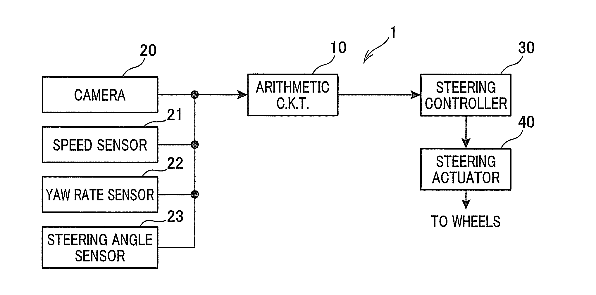
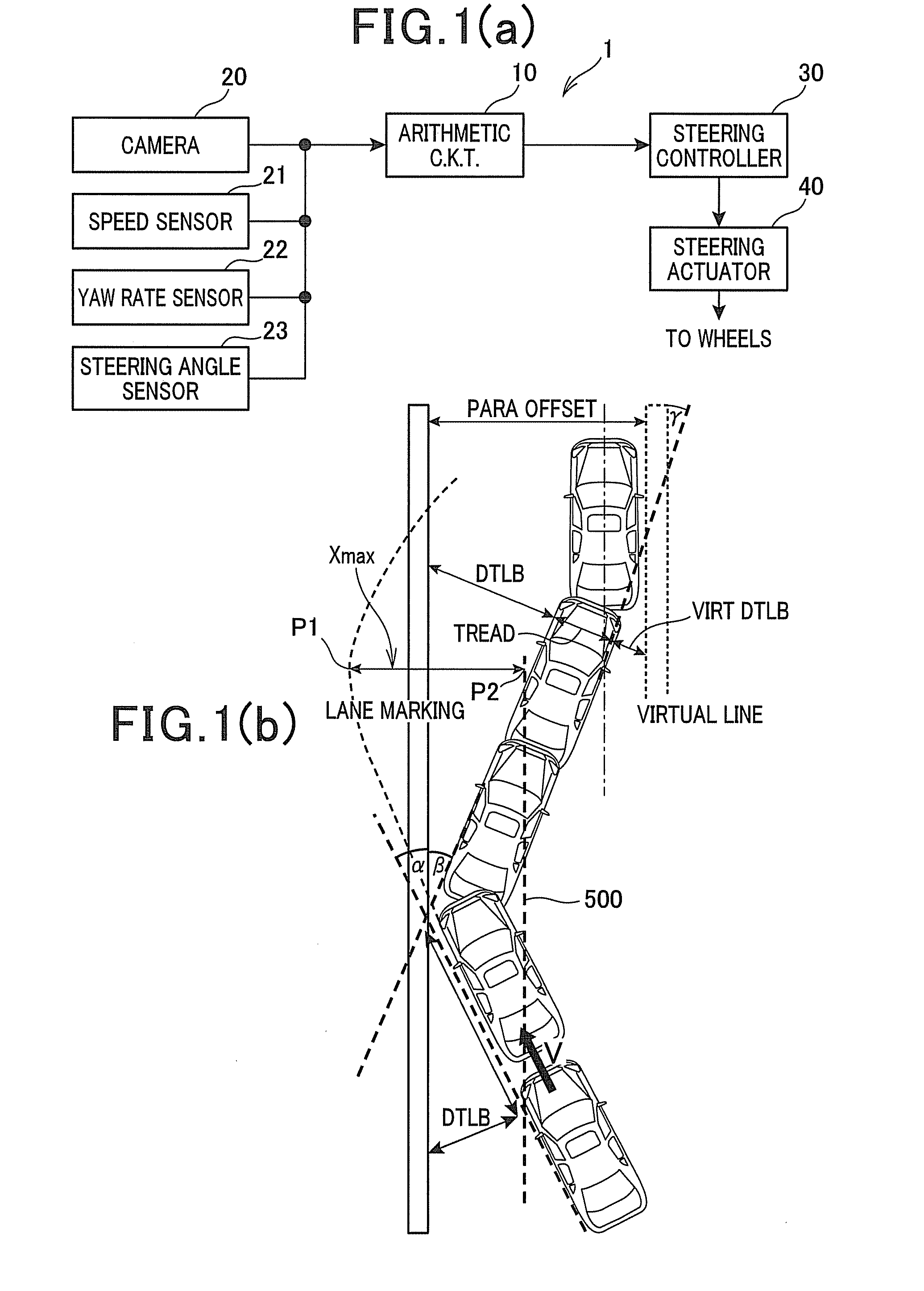
[0038]Referring to the drawings, wherein like reference numbers refer to like parts in several views, particularly to FIG. 1(a), there is shown a lane departure control system 1 for vehicles such as automobiles according to the first embodiment which may be used with a lane departure warning system.

[0039]In use, the lane departure control system 1 is mounted in a vehicle such as a passenger car and designed to keep that vehicle (which will also be referred to as a system vehicle below) within a traveling area or lane usually defined by right and left boundaries (i.e., lane lines) on a road.

[0040]The lane departure control system 1 is equipped with an arithmetic circuit 10, a camera 20, a vehicle speed sensor 21, a yaw rate sensor 22, a steering angle sensor 23, and a steering controller 30.

[0041]The arithmetic circuit 10 is implemented by a typical microcomputer equipped with a CPU, a ROM, a RAM, etc. and works as a lane departure controller to execute logic programs including a lan...


PUM


Abstract

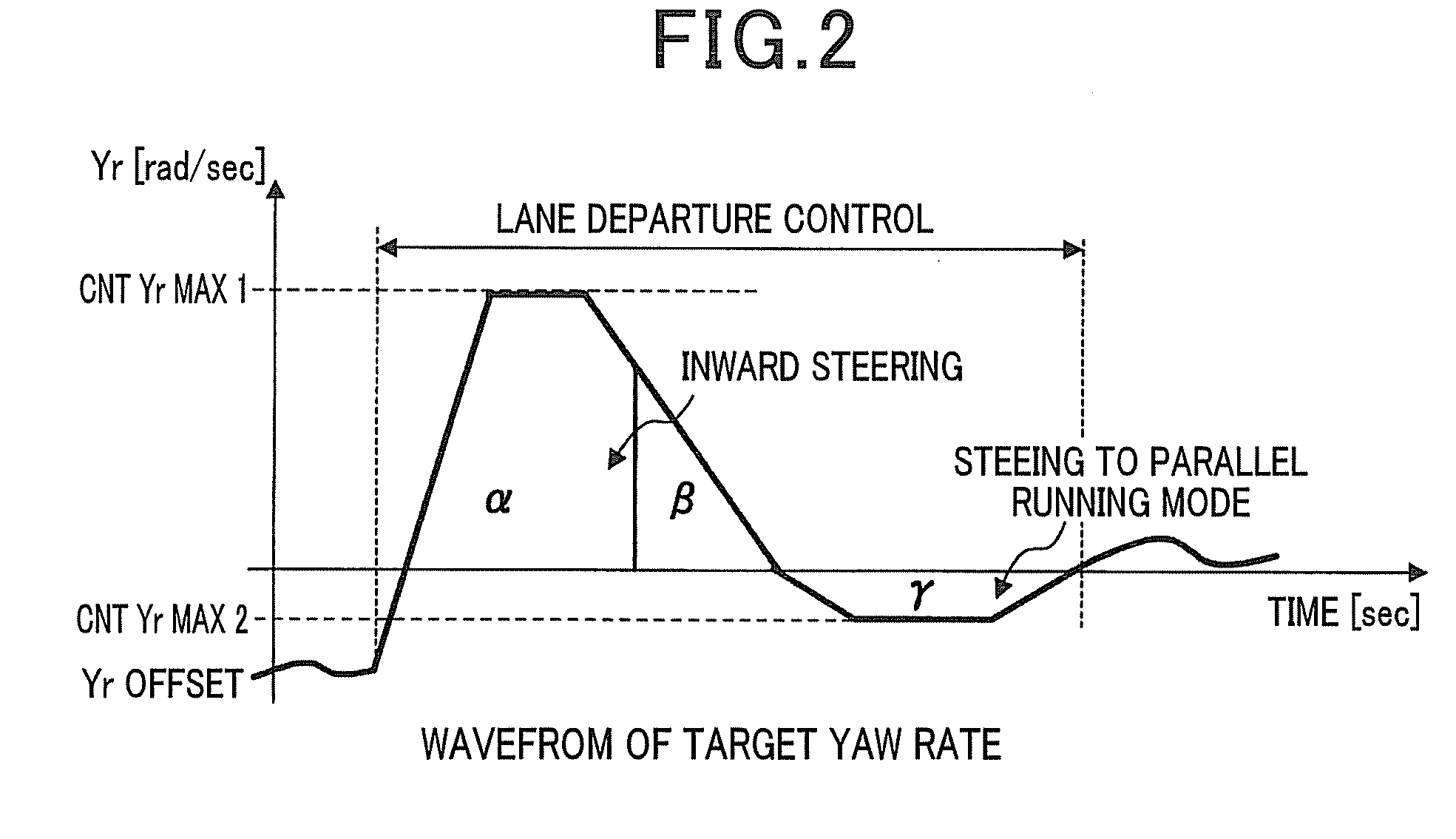
A lane departure control system is provided which steers a vehicle toward the center of a lane of a road at a first yaw rate by a controlled angle when the vehicle is determined to be about to deviate from the lane. Afterwards, when the vehicle is determined to be traveling toward a virtual line defined near a lane boundary, the system steers the vehicle by a correction angle so as to orient the vehicle parallel to the virtual line at a second yaw rate. The system changes the value of the first yaw rate at a first rate within the controlled angle and also changes the value of the second yaw rate at a second rate within the correction angle. An absolute value of the second rate is set smaller than that of the first rate, thereby minimizing an undesirable physical load on a driver of the vehicle.

Description

CROSS REFERENCE TO RELATED DOCUMENT[0001]The present application claims the benefit of priority of Japanese Patent Application No. 2012-13276 filed on Jan. 25, 2012, the disclosure of which is incorporated herein by reference.BACKGROUND OF THE INVENTION[0002]1 Technical Field[0003]This disclosure relates generally to a lane departure control system for vehicles which works to minimize the departure of a vehicle from its intended traveling zone, and more particularly to such a lane departure control system designed to control steering of the vehicle at a controlled yaw rate.2 Background Art[0004]Japanese Patent Publication No. 3800087 issued on May 12, 2006 teaches a lane departure prevention system for automotive vehicles which works to automatically steer the vehicle toward the center of a traveling lane thereof in a first steering control mode when the vehicle is determined to be likely to move out of the lane and then steer the vehicle in the opposite direction to keep the vehicl...

Claims


Application Information

Patent Timeline
IPC IPC(8): B62D6/00
CPCB62D6/00B62D15/025B62D6/003
Inventor NAKANO, TAKAHITOTATSUKAWA, JUNPEI
Owner DENSO CORP
Learn More