Method and apparatus for expendable tubing-conveyed perforating gun

a perforating gun and tubing technology, which is applied in the direction of fluid removal, earthwork drilling and mining, and wellbore/well accessories, etc., can solve the problems of inability to remove the outer and inner tubulars from the well without destroying the well and the impact resistance is low. , the effect of high strength

Active Publication Date: 2013-08-01
HALLIBURTON ENERGY SERVICES INC
View PDF4 Cites 54 Cited by
  • Summary
  • Abstract
  • Description
  • Claims
  • Application Information

AI Technical Summary

Benefits of technology

[0008]Methods and apparatus are presented for a “disappearing” perforator gun assembly. In a preferred method of perforating a well casing, inserted into the well casing is a tubing conveyed perforator having an outer tubular made from a metallic glass alloy having high strength and low impact resistance. An inner structure is positioned within the outer tubular and holds one or more explosive charges. Upon detonating the explosive charges, the outer tubular is fragmented. The inner structure is preferably also substantially destroyed upon detonation of the one or more explosive charges. For example, the inner structure can be made from a combustible material, corrodible, dissolvable, etc., material. Exemplary metallic glass alloys are Zr41.25 Ti13.75 Ni10 Cu12.5 Be22.5, Mg65 Cu25 Tb10, and Fe59 Cr6 Mo14 C15 B6. A disintegration-enhancing material is optionally positioned between the outer tubular and the inner structure.

Problems solved by technology

The outer and inner tubulars are often severely damaged, fragmented and misshapen during the process.
However, this method has several disadvantages since in many drilling situations the inner tubular on which the shaped charges are mounted is damaged to such a degree that it cannot be removed from the hole without destroying the well.
This extra drilling results in considerable additional time and drilling costs.
In addition, the conventional metal tubing used for the TCP assembly generally fragments into large pieces of debris upon firing of the charges.
These large pieces of metal debris often cause problems in fluid extraction, such as jamming of equipment, preventing tube removal, inhibiting fluid flow, contaminating the fluid, or clogging pumps or tubing used to extract the fluid.

Method used


Image

  • Method and apparatus for expendable tubing-conveyed perforating gun
  • Method and apparatus for expendable tubing-conveyed perforating gun
  • Method and apparatus for expendable tubing-conveyed perforating gun

Examples


Embodiment Construction

[0031]While the making and using of various embodiments of the present invention are discussed in detail below, a practitioner of the art will appreciate that the present invention provides applicable inventive concepts which can be embodied in a variety of specific contexts. The specific embodiments discussed herein are illustrative of specific ways to make and use the invention and do not limit the scope of the present invention. The description is provided with reference to a vertical wellbore; however, the inventions disclosed herein can be used in horizontal, vertical or deviated wellbores.

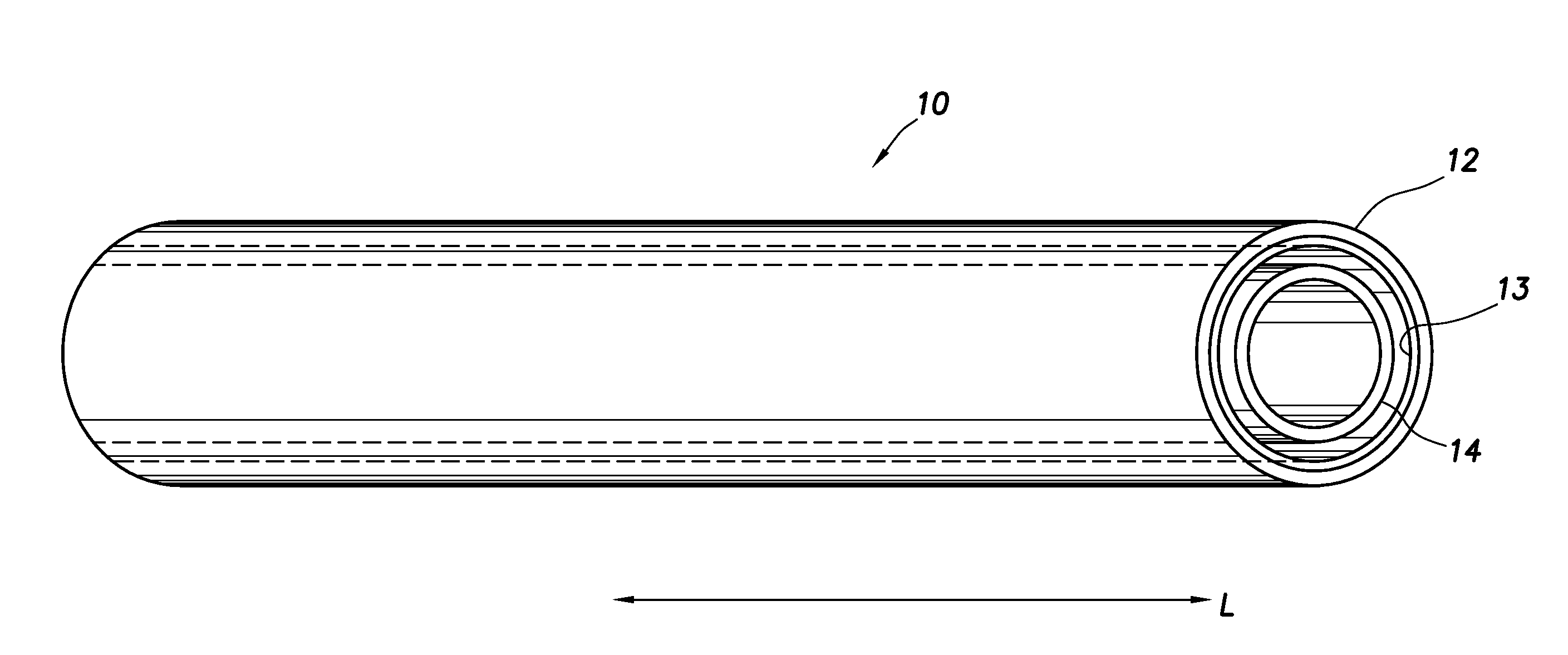
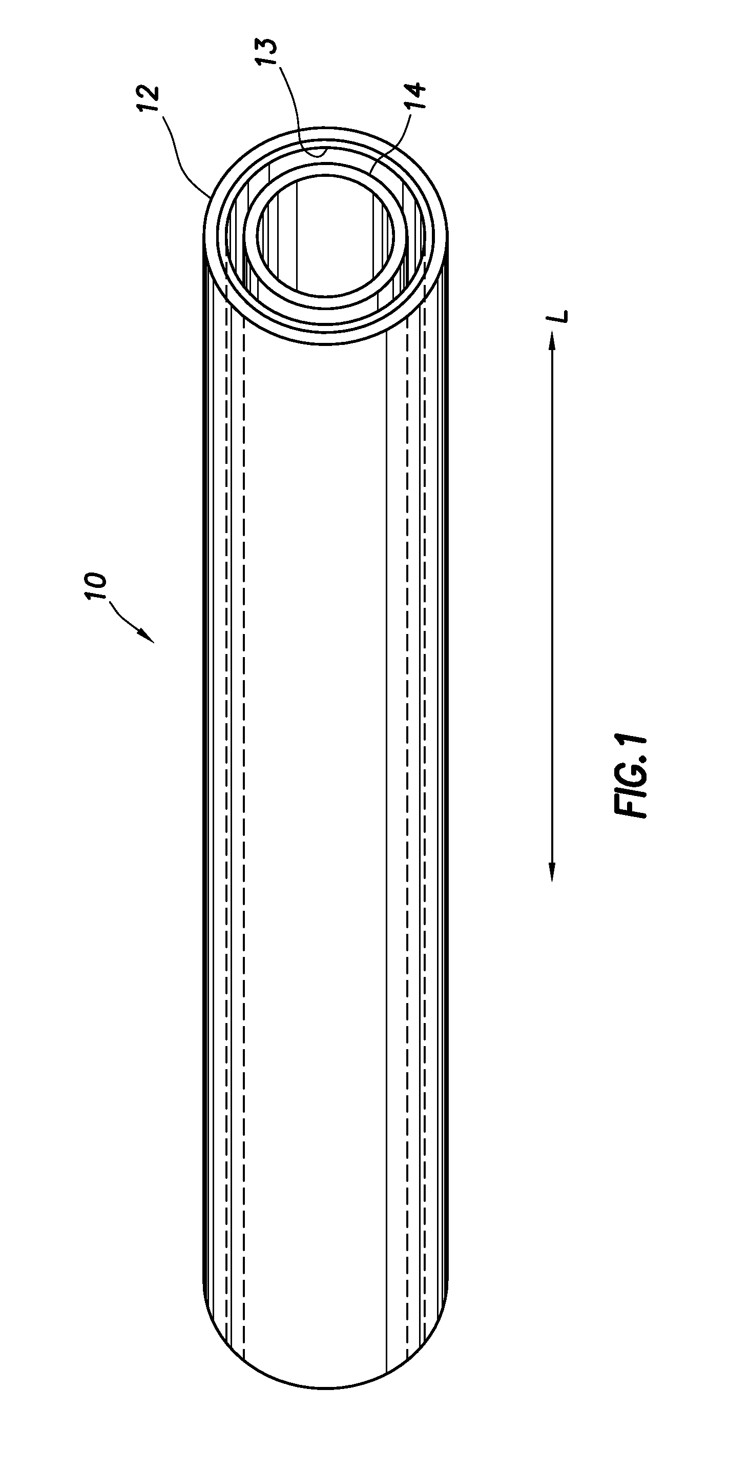
[0032]As described above, the invention is drawn to an expendable tubing conveyed perforator comprising an outer tubular made from a metallic glass alloy having high strength and low impact resistance and an inner structure made from a combustible material, the inner structure supporting one or more explosive charges. The present invention overcomes problems with prior art TCPs in that substa...


PUM


Abstract

Methods and apparatus are presented for a “disappearing” perforator gun assembly. In a preferred method of perforating a well casing, inserted into the well casing is a tubing conveyed perforator having an outer tubular made from a metallic glass alloy having high strength and low impact resistance. An inner structure is positioned within the outer tubular and holds one or more explosive charges. Upon detonating the explosive charges, the outer tubular is fragmented. The inner structure is preferably also substantially destroyed upon detonation of the one or more explosive charges. For example, the inner structure can be made from a combustible material, corrodible, dissolvable, etc., material. A disintegration-enhancing material is optionally positioned between the outer tubular and the inner structure. Additional embodiments are presented having gun housings which dematerialize upon detonation of the charges.

Description

CROSS-REFERENCE TO RELATED APPLICATIONS[0001]This application is a Continuation of U.S. application Serial No. 13 / 822,604 filed Mar. 12, 2013 which is a National Stage of International Application No. PCT / US2012 / 034599, filed Apr. 22, 2012 and claims priority to U.S. Provisional Application Ser. No. 61 / 477910, filed Apr. 21, 2011. Each patent application identified above is herein incorporated in its entirety by reference for all purposes.FIELD OF INVENTION[0002]The invention relates, in general, to a method and apparatus for perforating wells, and more particularly to an expendable tubing conveyed perforator assembly.BACKGROUND OF INVENTION[0003]Without limiting the scope of the present invention, its background will be described with reference to perforating a hydrocarbon bearing subterranean formation with a shaped-charge perforating apparatus.[0004]Two primary methods are extensively used to perform tubing-conveyed perforation (TCP) operations in the oil and gas recovery industr...

Claims


Application Information

Patent Timeline
Patent Type & Authority Applications(United States)
IPC IPC(8): E21B43/11
CPCE21B43/117E21B43/11
Inventor FADUL, JAVIERHERMAN, PAULRINGGENBERG, PAULMOORE, RANDYFRIPP, MICHAELCROWDIS, DENNISHALES, JOHNPOWELL, BRYAN
Owner HALLIBURTON ENERGY SERVICES INC
Why Eureka
Try Eureka