Multimodal vibration harvester combining inductive and magnetostrictive mechanisms

a multi-modal, magnetostrictive technology, applied in the field of energy harvesting, can solve problems such as limiting the amount of space needed

Active Publication Date: 2013-08-01
VIRGINIA TECH INTPROP INC
View PDF8 Cites 20 Cited by
  • Summary
  • Abstract
  • Description
  • Claims
  • Application Information

AI Technical Summary

Benefits of technology

[0012]Multi-Mechanism Energy Harvester (MMEH) devices with inductive and piezoelectric (e.g., magnetostrictive) mechanisms are provided by embodiments of the present invention. In preferred embodiments, multi-modal devices are provided within a package similar to the shape and size of an AA battery. Multi-modal devices of the present invention can also be scaled up to meet the requirements of additional applications, however, highly desired are energy harvesters having a form factor similar to that of an AA battery. For example, constraining the device to the size and shape of an AA battery enables replacement of one or more batteries within an existing battery housing, or otherwise limits the amount of space needed to accommodate an energy harvester module in addition to the battery housing.
[0014]A second mode or feature of embodiments of the invention is a magnetostriction mechanism, which capitalizes on the construction of the magnetic levitation cavity. In embodiments, the magnetostrictive mechanism consists of two clamped vibrating Galfenol discs at the top and bottom of the harvester. Ideally, the magnetostrictive discs are disposed at opposing ends of the cylindrical cavity. In embodiments, the magnetostrictive mechanism is made of Galfenol, which is preferred over Terfenol-D, to keep cost at a minimum. Such devices with this dual method of energy harvesting are expected to lead to higher power densities by increasing the volumetric efficiency.

Problems solved by technology

For example, constraining the device to the size and shape of an AA battery enables replacement of one or more batteries within an existing battery housing, or otherwise limits the amount of space needed to accommodate an energy harvester module in addition to the battery housing.

Method used


Image

  • Multimodal vibration harvester combining inductive and magnetostrictive mechanisms
  • Multimodal vibration harvester combining inductive and magnetostrictive mechanisms
  • Multimodal vibration harvester combining inductive and magnetostrictive mechanisms

Examples


Embodiment Construction

[0052]Reference will now be made in detail to various exemplary embodiments of the invention. It is to be understood that the following discussion of exemplary embodiments is not intended as a limitation on the invention. Rather, the following discussion is provided to give the reader a more detailed understanding of certain aspects and features of the invention.

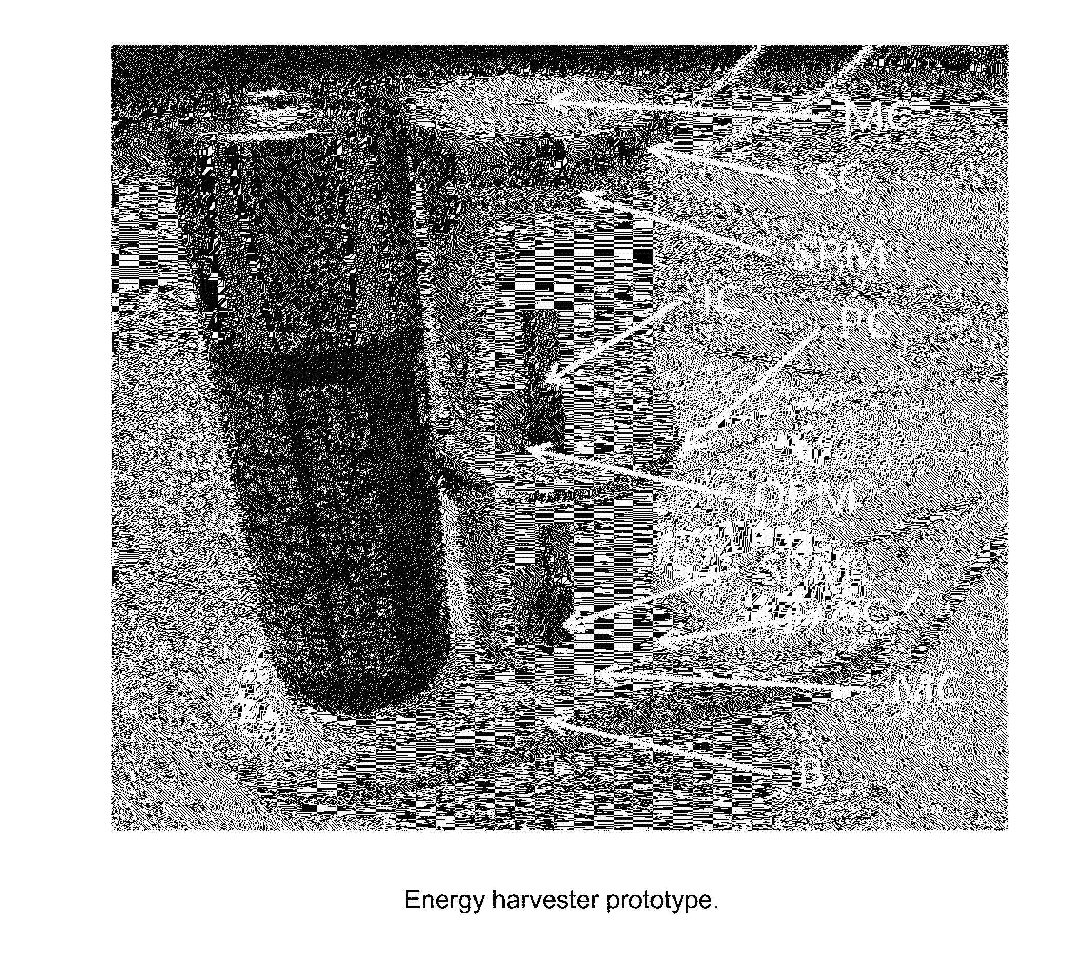
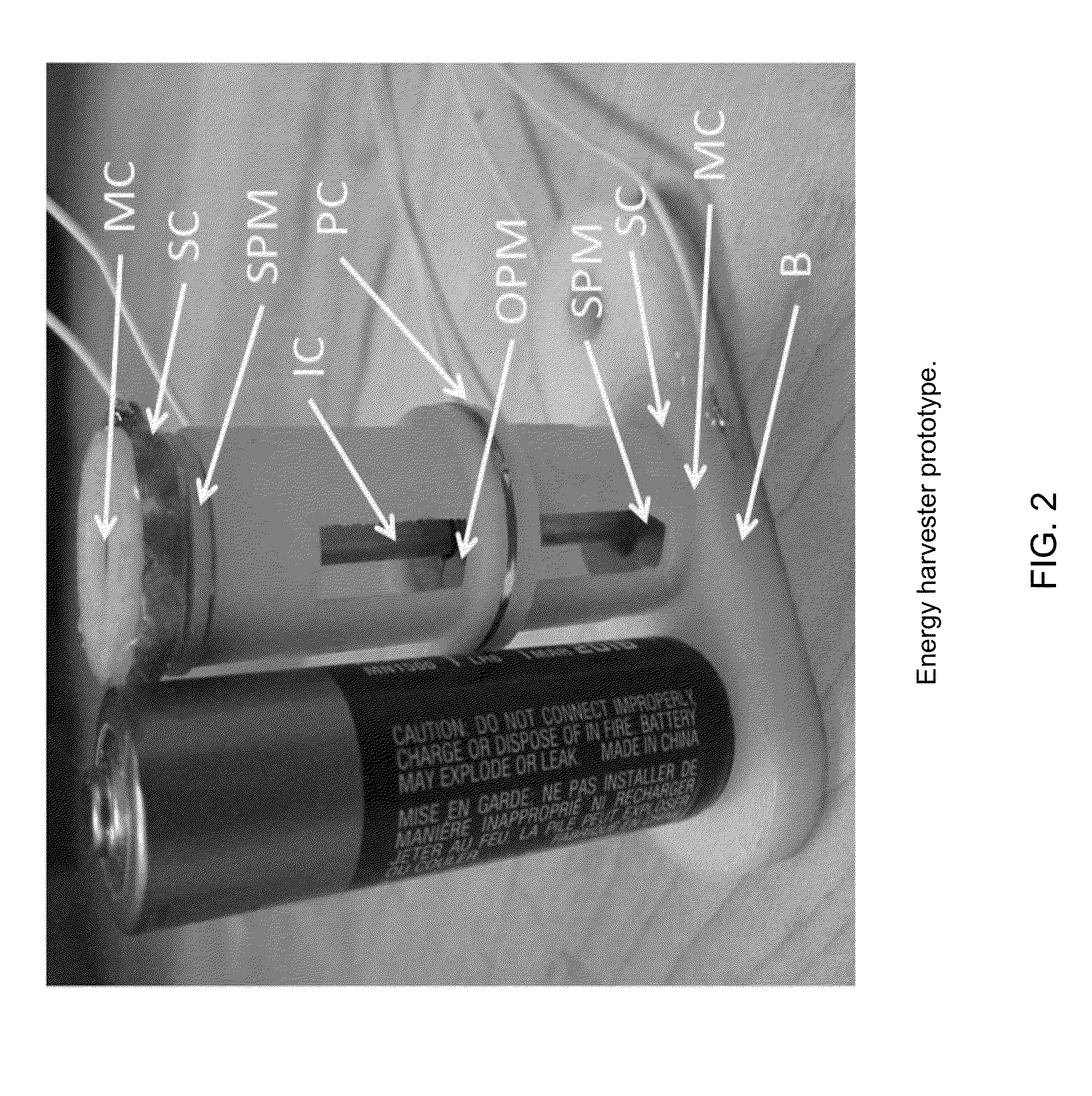
[0053]A CAD model of a representative multimodal energy harvester according to embodiments of the invention is shown in FIG. 2. As shown, the device preferably includes an outer housing (not shown) to cover a primary coil (PC) and two secondary coils (SC), an inner cover (IC) to support a coil and stainless steel rod (magnet bearing surface), stationary permanent magnets (SPM) at the top and bottom, an oscillating permanent magnet (OPM), a base (B) to attach to a vibration shaker, and a magnetostrictive cap (MC) material at the top and bottom. In embodiments, energy is harvested by two mechanisms: (1) from the magnetostricti...


PUM


Abstract

Multi-Mechanism Energy Harvesters (MMEHs) combining magnetostrictive and inductive mechanisms with a shape and size similar to an AA battery. Included are MMEHs with (a) an inductive mode: a cylindrical tube, a rod lengthwise within the tube, permanent magnets with opposing polarities at opposing ends of the tube, an annular oscillatory magnet in the tube and between the magnets and around the rod; and a primary coil around the tube and oscillatory magnet, such that relative movement between the magnet and coil induces electrical current in the coil; and (b) a magnetostrictive mode comprising: piezoelectric cymbal transducers on opposing ends of the tube and comprising a magnetostrictive material surrounded by a secondary coil, such that movement of the magnetostrictive material induces voltage in the secondary coil. During use, electrical energy can be harvested from the relative motion between the magnet and coil and from the magnetostrictive material.

Description

CROSS-REFERENCE TO RELATED APPLICATIONS[0001]This application relies on the disclosure of and claims priority to and the benefit of the filing date of U.S. Provisional Application No. 61 / 593,640, filed on Feb. 1, 2012, the disclosure of which is hereby incorporated by reference herein in its entirety.STATEMENT OF GOVERNMENT INTEREST[0002]This invention was made with government support under Grant No. IIP-1035042 awarded by National Science Foundation. The government has certain rights in the invention.BACKGROUND OF THE INVENTION[0003]1. Field of the Invention[0004]The present invention relates to the field of energy harvesting. More particularly, embodiments of the present invention relate to devices comprising at least two modes of energy harvesting, such as inductive and magnetostrictive mechanisms. Specific embodiments of the invention provide devices useful in structural health monitoring systems and other sensor technologies typically deployed on structures with limited accessi...

Claims


Application Information

Patent Timeline
Patent Type & Authority Applications(United States)
IPC IPC(8): H01L41/12F03G7/08H02K35/02
CPCH01L41/125H02N2/186F03G7/08H02K35/02H10N35/101
Inventor MARIN, ANTHONYPRIYA, SHASHANK
Owner VIRGINIA TECH INTPROP INC
Why Eureka
Try Eureka