
Adaptive radar systems with ecological microwave cameras

a technology of adaptive radar and microwave camera, applied in the field of ecological radar devices, can solve the problems of limited number of identical radars, inability to deploy existing radars independently, and all these sensors become useless

Active Publication Date: 2013-08-01
PAOLETTI PAOLO ALBERTO
View PDF10 Cites 46 Cited by
  • Summary
  • Abstract
  • Description
  • Claims
  • Application Information

AI Technical Summary

Benefits of technology

The present invention is a versatile and easy-to-use radar that can be adapted to different needs and applications. It is low-cost and can be used in a wide range of activities, especially in transportation. The radar uses a distributed radar system that integrates other elements based on the desired level of protection. It can be represented by a mathematical formula and can be modified and adapted for multiple devices. The technical effect of the invention is its adaptability and flexibility to meet the needs of security and protection.

Problems solved by technology

Unfortunately all these sensors become useless in case of thick fog, heavy rain, dense smog and similar prohibitive factors, because the particles in air suspension disperse the light rays, also the infra-red ones.
They are complex transmitter-receiver devices, irradiating electromagnetic power into a large frequency band; for this reason unfortunately they are considerable sources of electromagnetic noise, at the point that more identical radars cannot work together without disturbing each other, unless they be distant enough or used distant frequency bands: the availability of which is limited anyway, and therefore is limited also the number of identical radars let working together in a same area.
This means that existing radars cannot be deployed independently at will as it happens for cited video cameras.
All this variety of applications is of course impossible with conventional stand alone radars, which are all “monolithic” devices even if internally made up by modules or mini-radars performing elementary functions, because such modules stay all together inside the same assembly and are synchronized all at once, and therefore they are not independent, not self contained, not autonomous, not suitable to be “distributed” at will over long distances.

Method used


Image

  • Adaptive radar systems with ecological microwave cameras
  • Adaptive radar systems with ecological microwave cameras
  • Adaptive radar systems with ecological microwave cameras

Examples


Embodiment Construction

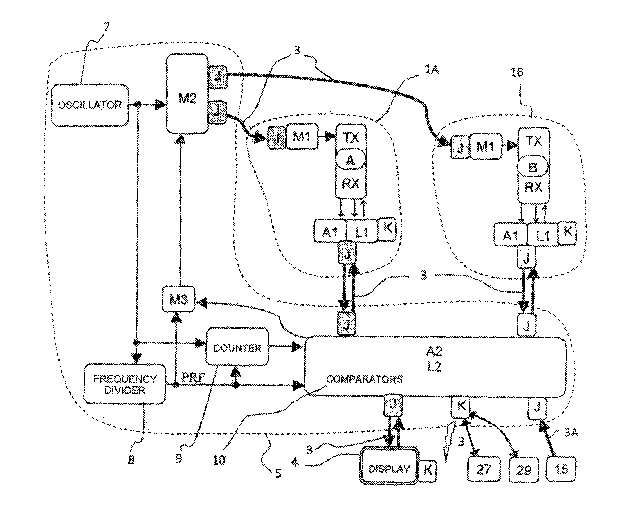
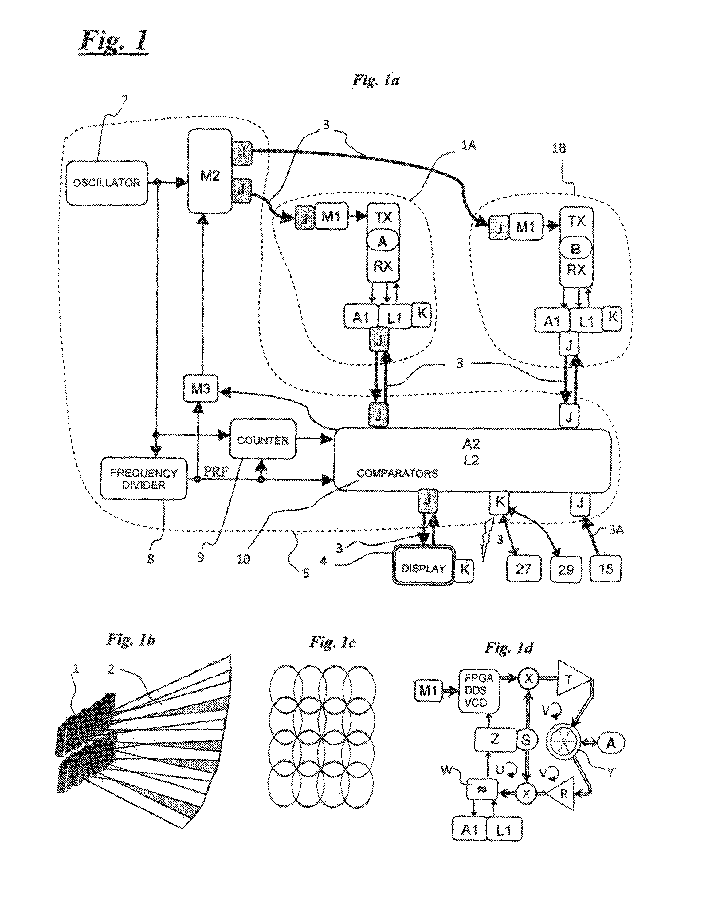
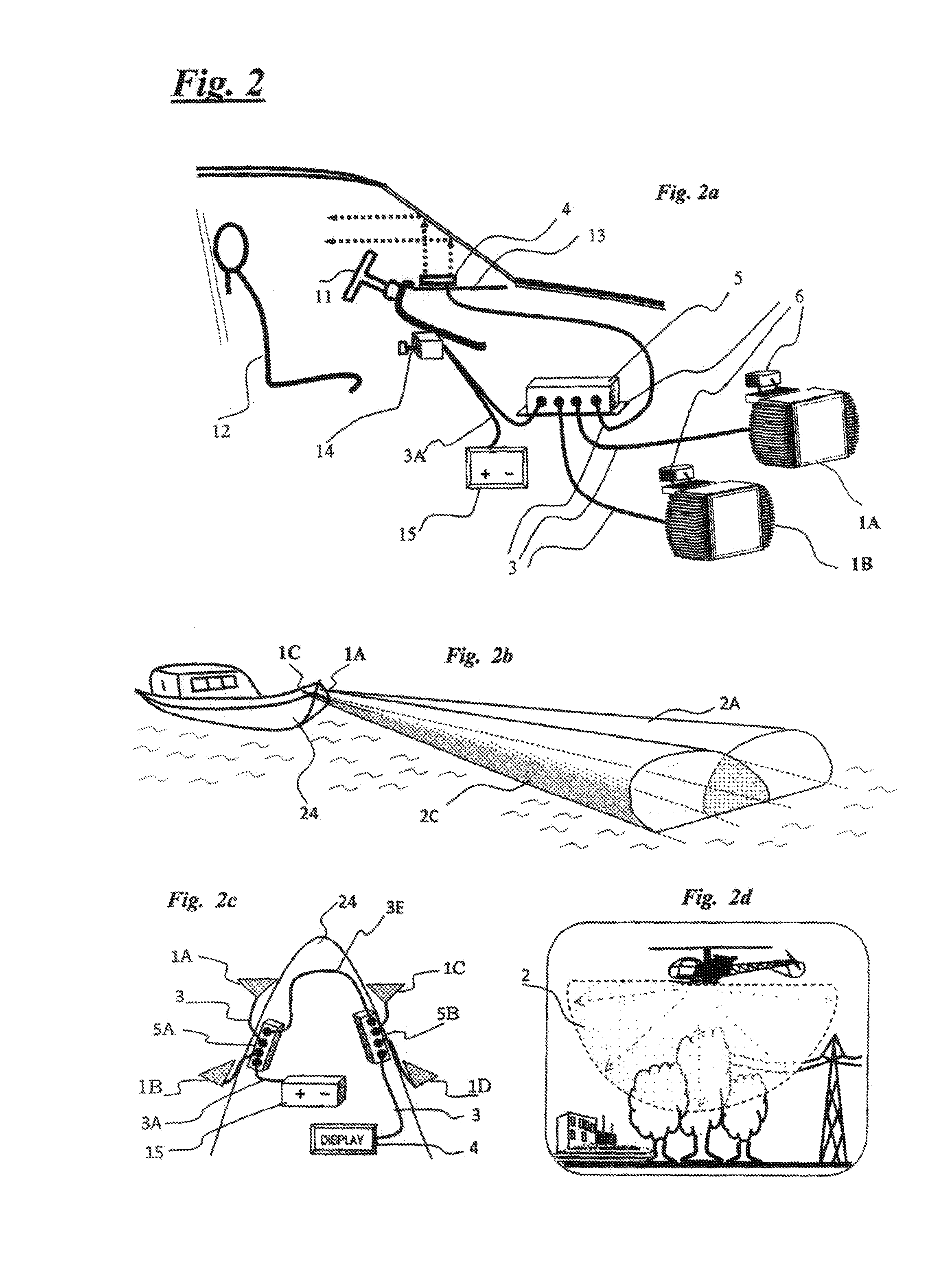
[0016]The present invention, being able to assume any attitude, is extremely versatile, easy to use and low cost, valid to satisfy a wide variety of applications still uncovered. It falls within the substantive scope of human needs and in the technical field of electronic equipment manufacturing. As mentioned, it includes a distributed radar that integrates other elements, depending on the use and the degree of protection desired. This radar can also be represented by the following mathematical formula

u(t)=r(t)·m(t)=A2·cos(ϕ2+2πf2t)·A1·cos(2πf1t+ϕ1)==A·cos[2π(f1+f2)t+(ϕ1+ϕ2)]+A·cos[2π(f2-f1)t]+(ϕ2-ϕ1)]

and its possible modification, adaptation and combinations for a plurality of concurring devices, bearing in mind that the most significant aspect of the invention lies in the fact that it is adaptive and adaptable to the needs of security, increasingly felt by the modern society for all sorts of activities and especially in transportation.

[0017]The invention is disclosed in the append...


PUM


Abstract

Surveillance system for detecting the position, movement, nature of one or more objects and even communicate with it, that is adaptive to any extent and suitable for any mobile or fixed structure and even for persons, because of its flexible open architecture, which is fully modular to develop self-contained compact radar devices of special performances when working either autonomously, like conventional video-cameras nevertheless operating also with microwaves and therefore called microwave-cameras or radar-cameras, or jointly to form more complex interactive systems.

Description

FIELD OF THE INVENTION[0001]The invention refers to ecological radar devices to precisely detect objects in any weather condition and zero visibility, suitable to form surveillance and safety systems adaptive to any extent and to any mobile or fixed structures, such as vehicles, roads, rails, tunnels, canals, platforms, buildings, harbours, airports, and even to persons.PRIOR ART AND PURPOSE OF THE INVENTION[0002]There are many “critical infrastructures”, such as those destined to transportation, which demand surveillance and protection and for which plenty of measures have been deployed, essentially based on video-surveillance by means of electro-optical sensors such as daylight video cameras and night vision infrared cameras. Unfortunately all these sensors become useless in case of thick fog, heavy rain, dense smog and similar prohibitive factors, because the particles in air suspension disperse the light rays, also the infra-red ones.[0003]Then to explore such invisible scenario...

Claims


Application Information

Patent Timeline
Patent Type & Authority Applications(United States)
IPC IPC(8): G01S13/04G01S13/86G01S13/931G01S13/933G01S13/937
CPCG01S13/04G01S13/87G01S13/9303G01S13/9307G01S13/931G01S13/867G01S2013/9385G01S2013/9353G01S2013/9357G01S2013/9375G01S2013/9378G01S2013/9382G01S2013/9339G01S2013/93273G01S2013/9322G01S2013/9329G01S13/937G01S13/933G01S2013/93274G01S2013/93272G01S2013/932G01S2013/93271
Inventor PAOLETTI, PAOLO ALBERTO
Owner PAOLETTI PAOLO ALBERTO
Learn More