Dynamic-grid comb optical source

a dynamic grid and optical source technology, applied in the field of optical sources, can solve the problems of complex wavelength control of such existing wdm optical sources, difficulty in implementing wdm silicon-photonic links, and difficulty in finding suitable low-cost wdm optical sources, and achieve the effect of maintaining wavelength registration

Active Publication Date: 2013-08-01
ORACLE INT CORP
View PDF6 Cites 15 Cited by
  • Summary
  • Abstract
  • Description
  • Claims
  • Application Information

AI Technical Summary

Benefits of technology

[0013]Note that the control signals may adjust gains, phases and emitting wavelengths of the set of light sources, thereby substantially maintaining registration of the wavelengths in the wavelength comb output by the optical device. For example, the set of light sources may include ring resonators having resonant wavelengths, and the control signals may adjust the source emitting wavelengths by adjusting the resonant wavelengths.

Problems solved by technology

However, a suitable low-cost WDM optical source, such as a multi-wavelength laser source, remains a challenge and, in its absence, poses an obstacle to implementing WDM silicon-photonic links.
However, wavelength control for such existing WDM optical sources is typically quite complicated.
For example, air-gap etalon filters are often used in the existing WDM optical sources to implement wavelength locking These air-gap etalon filters are usually bulky, and therefore are not suitable for integration or for use in WDM silicon-photonic links in which there may be thousands of integrated WDM optical sources.

Method used


Image

  • Dynamic-grid comb optical source
  • Dynamic-grid comb optical source
  • Dynamic-grid comb optical source

Examples


Embodiment Construction

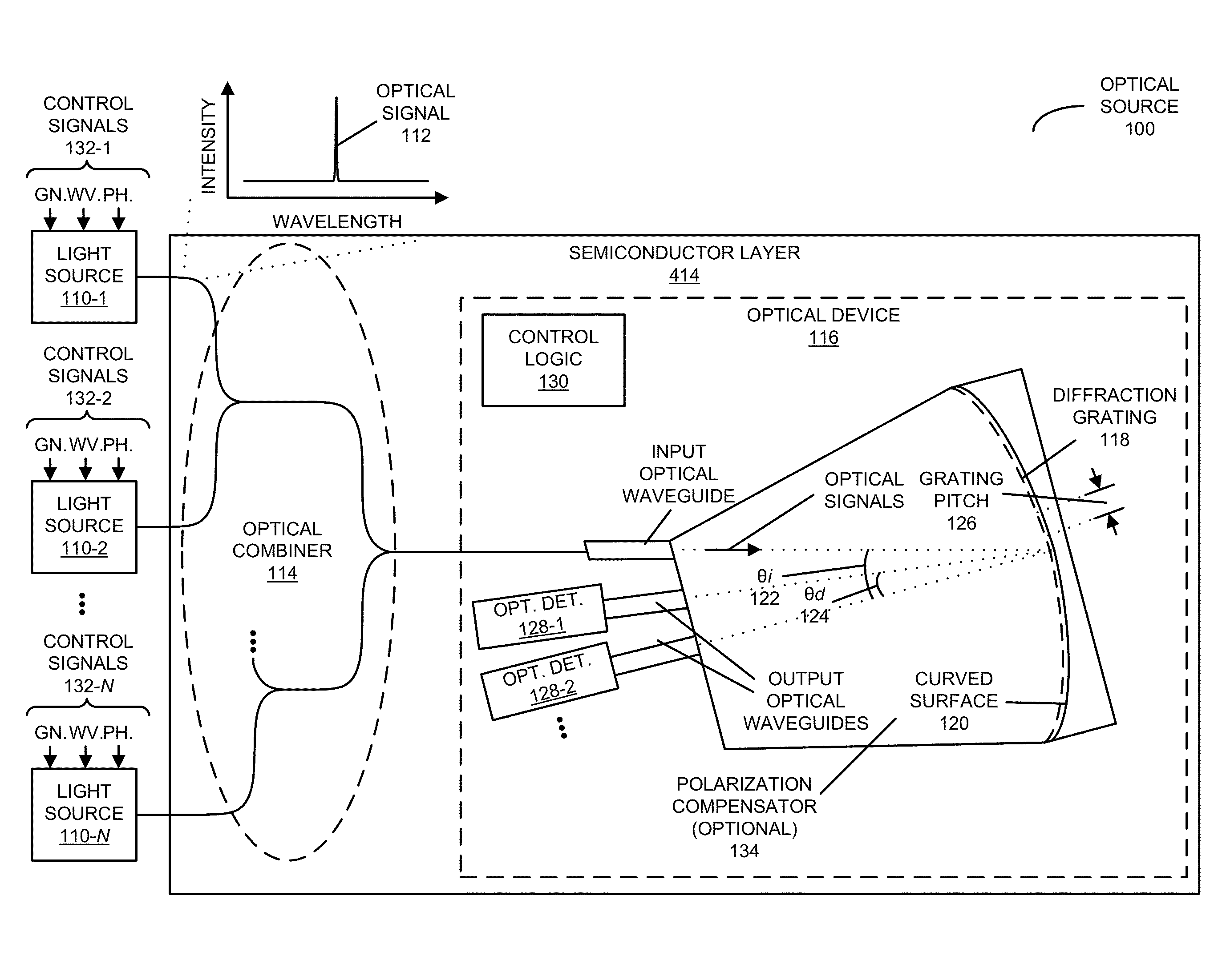
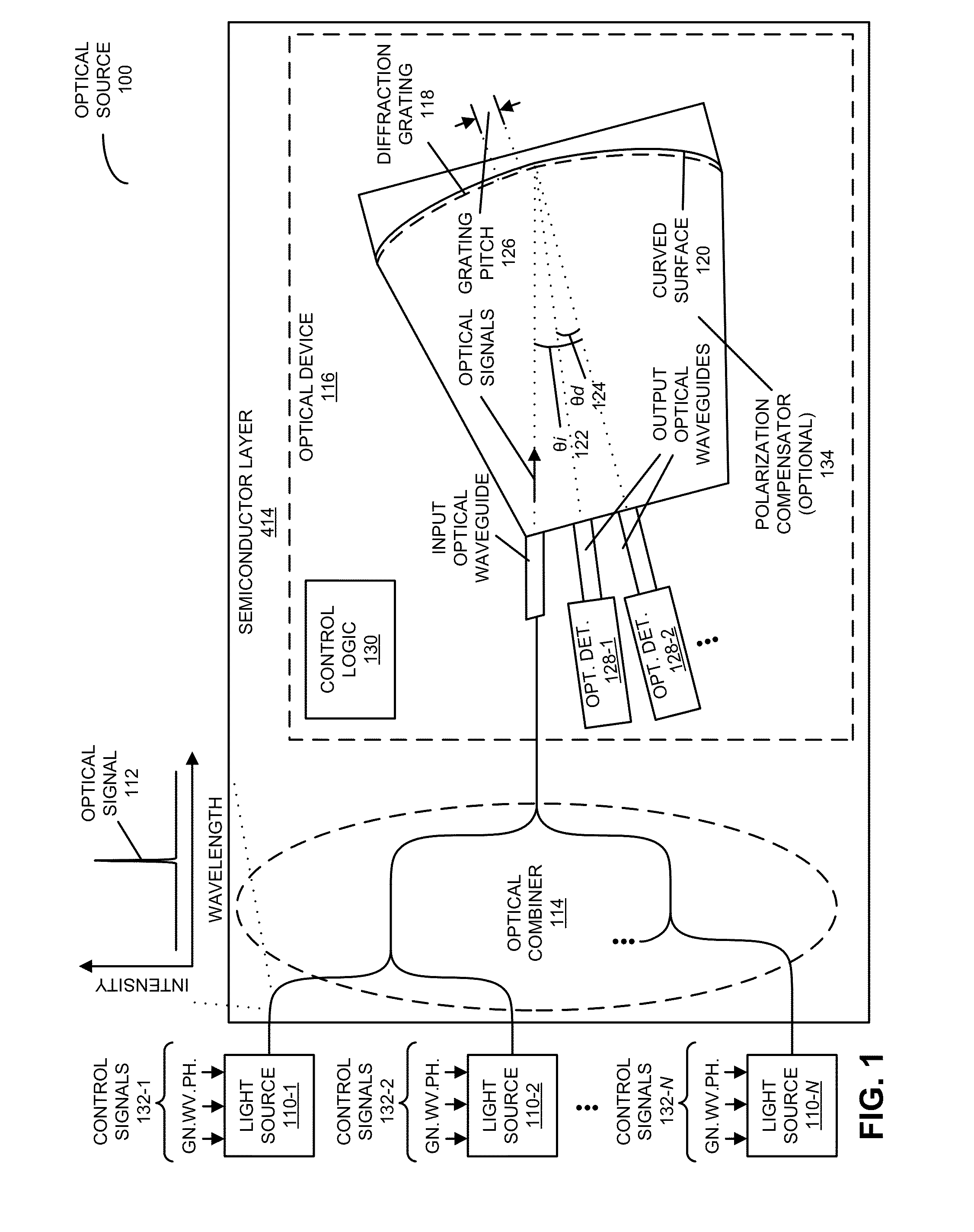
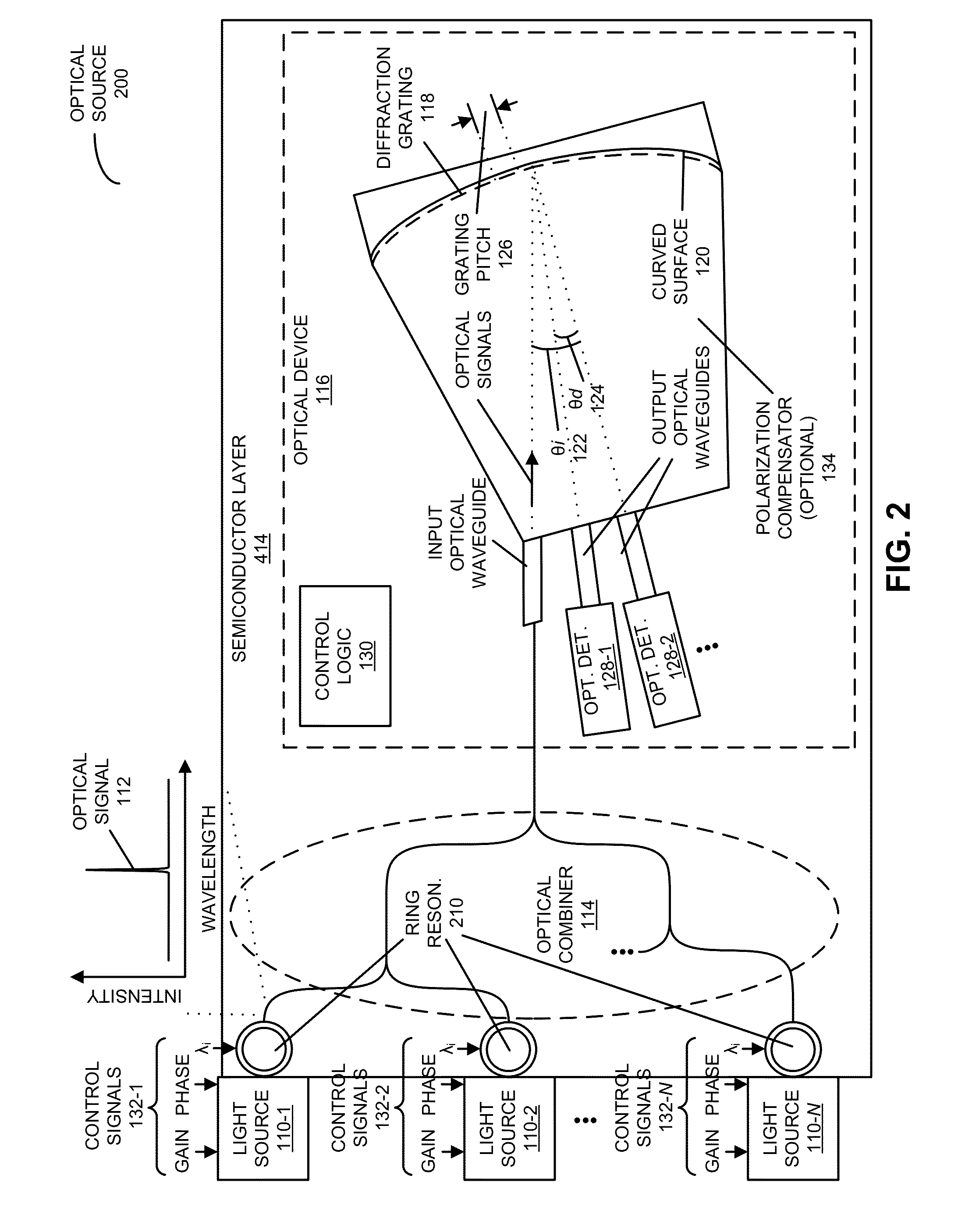
[0024]Embodiments of an optical source, a system that includes the optical source, and a technique for providing optical signals are described. This optical source uses feedback to maintain a substantially fixed spacing between adjacent wavelengths in a set of wavelengths in a wavelength comb output by the optical source. In particular, a set of light sources in the optical source provide optical signals having the set of wavelengths. Moreover, the optical signals are output at diffraction angles of an optical device in the optical source (such as an echelle grating), and optical detectors in the optical source determine optical metrics associated with the optical signals. Furthermore, control logic in the optical source provides control signals to the set of light sources based on the determined optical metrics.

[0025]By providing a wavelength comb with substantially fixed spacing between adjacent wavelengths, the optical source may allow a compact, energy-efficient, low-cost, multi...


PUM


Abstract

An optical source uses feedback to maintain a substantially fixed spacing between adjacent wavelengths in a set of wavelengths in a wavelength comb output by the optical source. In particular, a set of light sources in the optical source provide optical signals having the set of wavelengths. Moreover, the optical signals are output at diffraction angles of an optical device in the optical source (such as an echelle grating), and optical detectors in the optical source determine optical metrics associated with the optical signals. Furthermore, control logic in the optical source provides control signals to the set of light sources based on the determined optical metrics.

Description

GOVERNMENT LICENSE RIGHTS[0001]This invention was made with Government support under Agreement No. HR0011-08-9-0001 awarded by DARPA. The Government has certain rights in the invention.BACKGROUND[0002]1. Field[0003]The present disclosure relates to techniques for communicating optical signals. More specifically, the present disclosure relates to an optical source that uses feedback to maintain a substantially fixed spacing between adjacent wavelengths produced by the optical source.[0004]2. Related Art[0005]Silicon photonics is a promising technology that can provide large communication bandwidth, low latency and low power consumption for inter-chip and intra-chip connections. In the last few years, significant progress has been made in developing low-cost components for use in inter-chip and intra-chip silicon-photonic connections, including: high-bandwidth efficient silicon modulators, low-loss optical waveguides, wavelength-division-multiplexing (WDM) components, and high-speed C...

Claims


Application Information

Patent Timeline
Patent Type & Authority Applications(United States)
IPC IPC(8): H04B10/04H04J14/02H04B10/08
CPCH04B10/506G02B6/29308H04J14/02H04B10/572
Inventor ZHENG, XUEZHELUO, YINGLI, GUOLIANGKRISHNAMOORTHY, ASHOK V.
Owner ORACLE INT CORP
Why Eureka
Try Eureka