
Heatsink for electronic component

a technology for electronic components and heat sinks, applied in the field of heat sinks, can solve the problems of electronic components, electronic components may become damaged, and two methods cannot be applied to materials having a high thermal conductivity, and achieve the effect of maintaining registration and preventing distortion of binding portions

Inactive Publication Date: 2005-04-26
ZALMAN TECH CO LTD
View PDF14 Cites 55 Cited by
  • Summary
  • Abstract
  • Description
  • Claims
  • Application Information

AI Technical Summary

Benefits of technology

"The present invention provides a heatsink for cooling a heat-generating electronic component without the need for a fan, which has low thermal resistance and does not generate noise. The heatsink plates have binding portions and heat-dissipating portions with a plurality of heat-dissipating fins. The heatsink plates can be bent at angles relative to the binding portions to increase separation between adjacent heat-dissipating portions. The heatsink plates can be bound together with a binding material, such as a clip fitting or a plurality of spacers, and each heat-dissipating fin has a protrusion that contacts an adjacent fin to prevent distortion of the binding portions. The heatsink plates can be used in an electronic apparatus with an electronic component by simply binding them together and contacting the heat-dissipating surface of the component. The technical effects of the invention are improved cooling efficiency, reduced power consumption, and reduced noise."

Problems solved by technology

If an electronic component is heated over a predetermined temperature, an error may occur in the electronic component, or the electronic component may become damaged.
However, these two methods cannot be applied to some materials having a high thermal conductivity, for example, to copper (Cu) which has a higher thermal conductivity than Al alloy.
Also, the conventional methods do not provide the heatsink with a sufficiently large heat dissipating area and heat conducting area, and with a short thermally conductive pathway.
Thus, a highly thermally conductive material cannot be used to manufacture the heatsink, and the heat conducting area and heat dissipating area of the heatsink are not large enough for effective heat transfer.
Although the heatsink has a large heat dissipating area, the heat conducting efficiency is low due to the long thermally conductive pathway, small heat conducting area, and the presence of a heat transfer boundary.
As set forth above, the conventional heatsink requires a fan for appropriate heat dissipation, which has the inherent problems of high power consumption, noises and scattering and sticking of dust.
However, heat generated by CPUs hinders speed increases of CPUs.

Method used


Image

  • Heatsink for electronic component
  • Heatsink for electronic component
  • Heatsink for electronic component

Examples


Embodiment Construction

[0038]A good heatsink should effectively absorb the heat generated by heat-generating parts without power consumption and without generating noise and vibrations, and transfer the absorbed heat into the surrounding air. Also, the manufacturing process should be easy. That is, a good heatsink is a heatsink capable of keeping the temperature of the heat-generating parts at the lowest level without using a cooling fan, and can be made easily. In addition, by installing a fan capable of forcibly blowing air over and around the heatsink, the heat dissipating efficiency can be further increased.

[0039]The technical idea of a heatsink according to the present invention, for satisfying the above conditions, is to manufacture a heatsink through a pressing process, which allows a plurality of heatsink units to be stacked on one another, using aluminum (Al) or copper (Cu) having a high thermal conductivity as the material, such that the thermally conductive pathway can be as short as possible. ...


PUM


Abstract

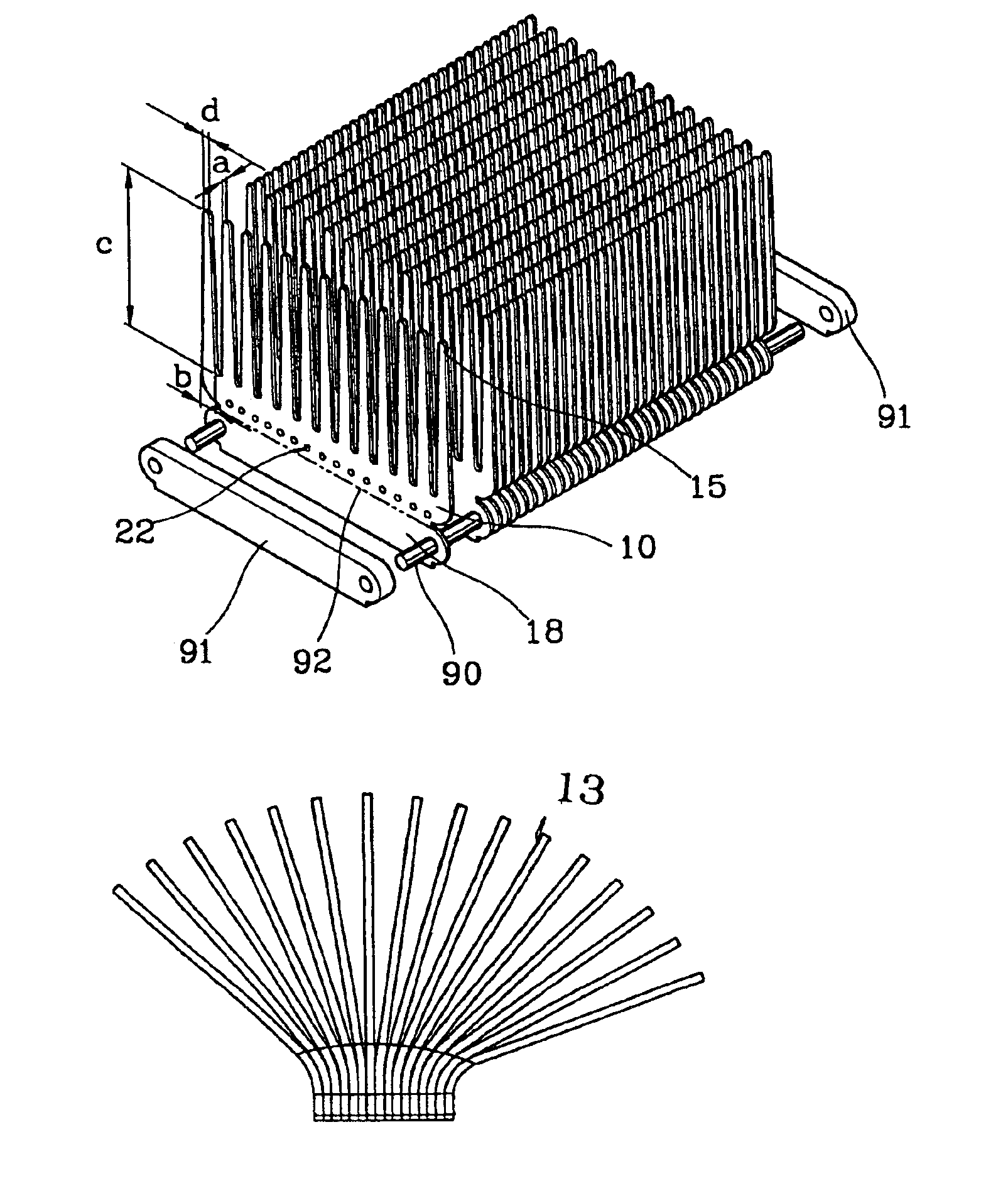
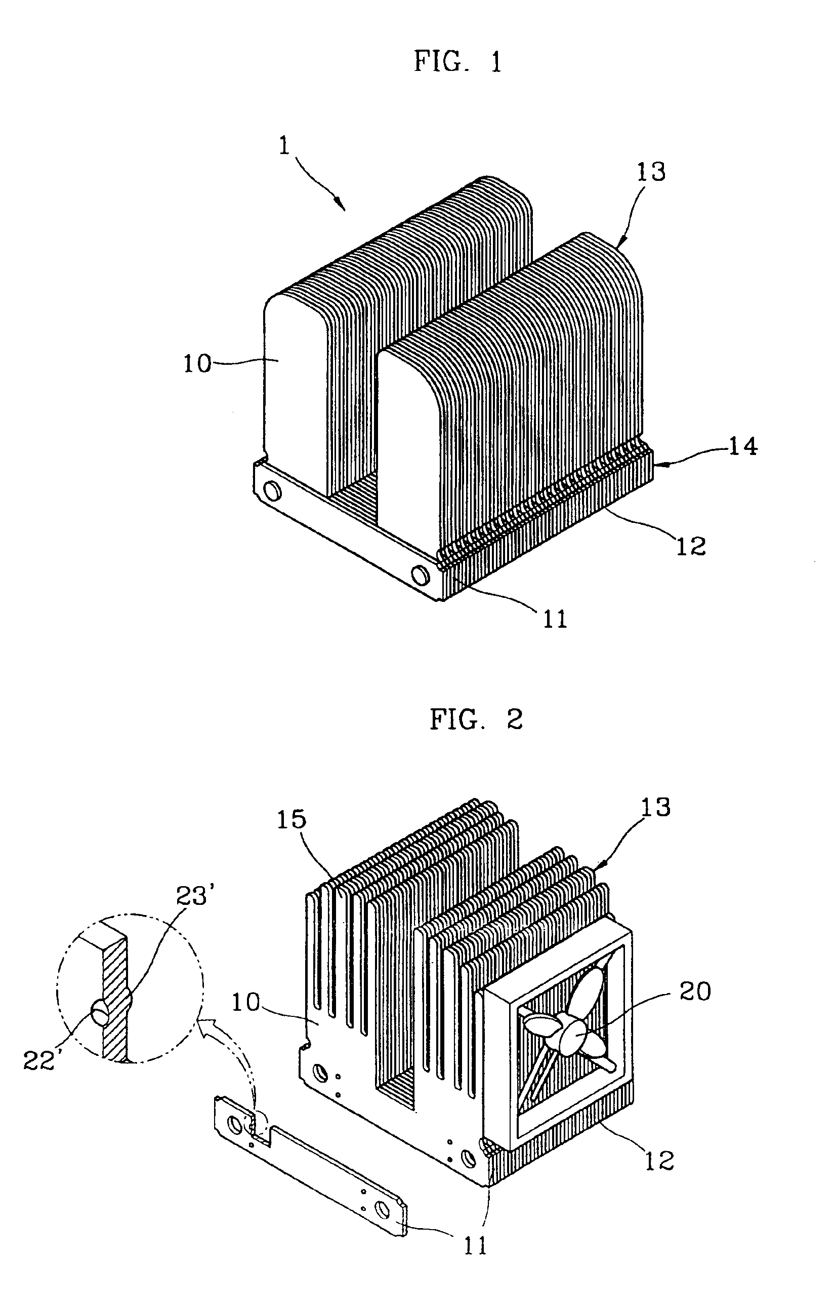
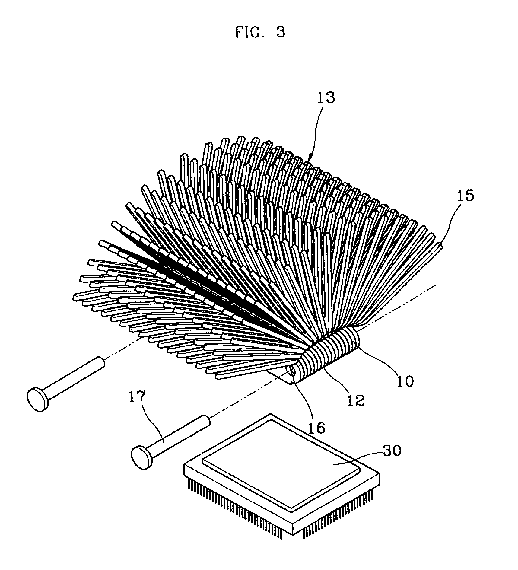
A heatsink for dissipating heat from a heat-generating source such as an electronic component includes heatsink plates, wherein the individual heatsink plates are bound together at a binding portion to form a heat-absorbing portion for contacting a heat-dissipating surface of the electronic component, and portions of the heatsink plates opposite the heat-absorbing surface are separated from each other to collectively act as a heat-dissipating portion binding the heatsink plates together. To provide the separation between heat-dissipating portions of the heatsink plates, the heatsink includes spacers interposed between the binding portions of neighboring heatsink plates or the heatsink plates are spread out apart from each other by being bent at angles. The heatsink plates include fins spaced apart from each other at an interval. The binding element is preferably a rivet. In manufacturing the heatsink, a protrusion is formed at the individual heatsink plates such that the heat dissipating portion of the heatsink is unfolded outward at a angle by the protrusion. The heatsink can transfer the heat generated from a heat-generating source into the surrounding air, without power consumption and without generation of noise and vibrations, and such a heatsink can easily be manufactured.

Description

[0001]This disclosure is a continuation-in-part of U.S. patent application Ser. No. 09 / 433,884 filed Nov. 4, 1999 now abandoned.BACKGROUND OF THE INVENTION[0002]1. Field of the Invention[0003]The present invention relates to a heatsink for dissipating heat from electronic components, such as components of a computer system.[0004]2. Description of the Related Art[0005]Central processing units (CPUs), thermoelectric modules, power transistors, video graphics array (VGA) chips, radio frequency chips and the like are examples of electronic components. Since such electronic components produce a large amount of heat during operation, effective cooling is an important concern. If an electronic component is heated over a predetermined temperature, an error may occur in the electronic component, or the electronic component may become damaged. For this reason, heatsinks are installed on such electronic components and dissipate generated heat into the air, thus lowering the temperature of the ...

Claims


Application Information

Patent Timeline
Patent Type & Authority Patents(United States)
IPC IPC(8): H01L23/467H01L23/367H01L23/40H01L23/34
CPCH01L23/3677H01L23/4093H01L23/467H01L2023/4056H01L2924/0002H01L2023/4087H01L2924/00
Inventor LEE, SANG-CHEOL
Owner ZALMAN TECH CO LTD
Learn More