Inclined manhole cover riser assembly

a manhole cover and assembly technology, applied in the direction of artificial islands, foundation engineering, construction, etc., can solve the problems of depression in the roadway, difficulty and cost of raising the existing manhole frame sufficiently, and the resurfacing of the roadway

Inactive Publication Date: 2013-08-01
AMERICAN HIGHWAY PRODS
View PDF5 Cites 5 Cited by
  • Summary
  • Abstract
  • Description
  • Claims
  • Application Information

AI Technical Summary

Benefits of technology

[0013]A riser assembly and method for engaging the same to raise a manhole cover to be flush with an inclined paved surface after the application of an additional layer of paving material thereto. The riser assembly includes a first and second riser frame with a plurality of specially manufactured spacer blocks fixedly secured between them. The spacer blocks have progressively different height dimensions and sloped upper surfaces so as to creat

Problems solved by technology

Problems arise in the resurfacing of the roadways when a layer of pavement is placed on top of the existing pavement.
This results in the manhole cover being positioned a distance below the top surface of the new pavement, causing a depression in the roadway.
It is quite difficult and expensive to raise the existing manhole frame sufficiently to compensate for the added pavement.
However, when the pavement surface is inclined, as would be the case if the manhole were located on a hill or in a valley, for example, then the riser assembly disclosed in U.S. Pat. No. 7,165,911 is not entirely adequate for the job.
Either of this situations leads to early degradation of the new pavement surface and simultaneously tends to be hazardous for vehicles traveling over the road.
One of the issues with this device is that it requires the road crew installing it to make a series of calculations and adjustments to the device while they are busy installing the same.
This need for doing calculations in the field tends to slow the installation process down.
The device is therefore limited to riser heights that are greater than the thickness of the manhole cover plus the thickness of the top ring.
This arrangement is impractical in many instances because t

Method used


Image

  • Inclined manhole cover riser assembly
  • Inclined manhole cover riser assembly
  • Inclined manhole cover riser assembly

Examples


Embodiment Construction

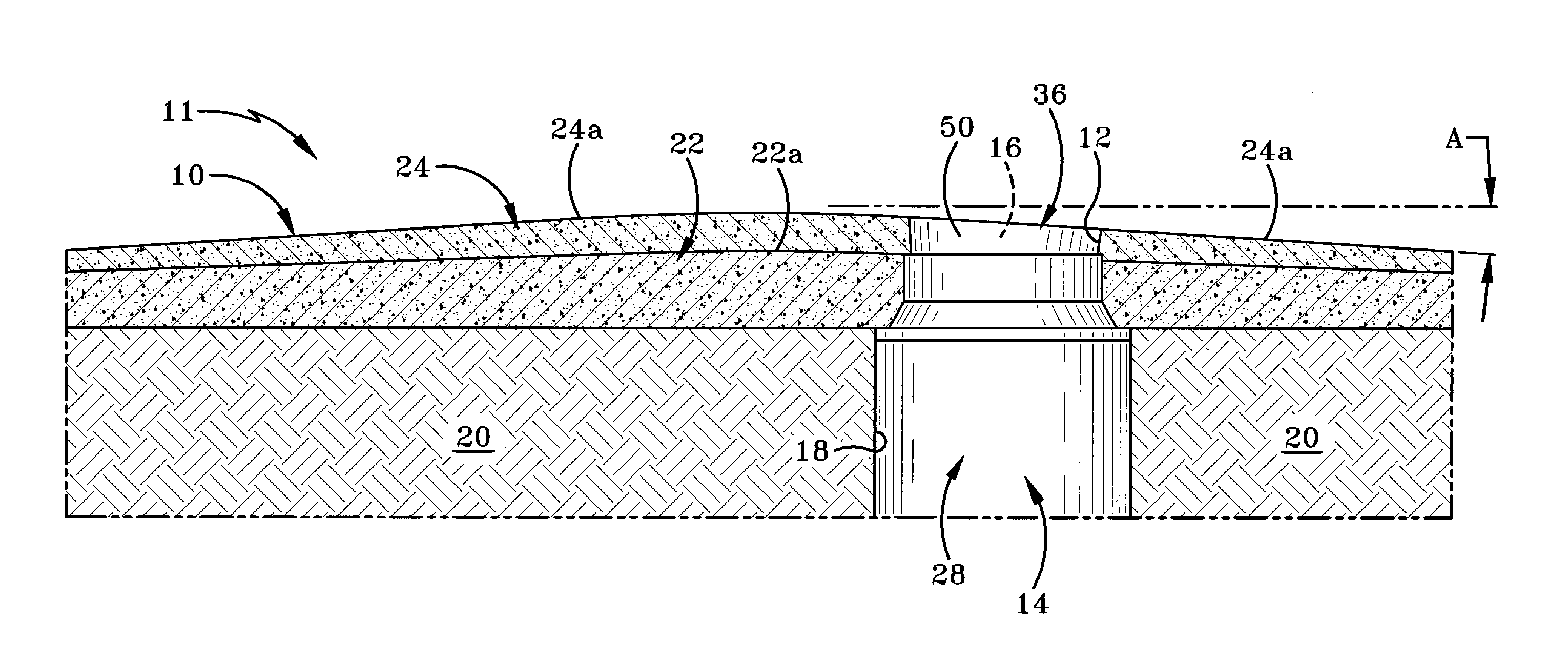
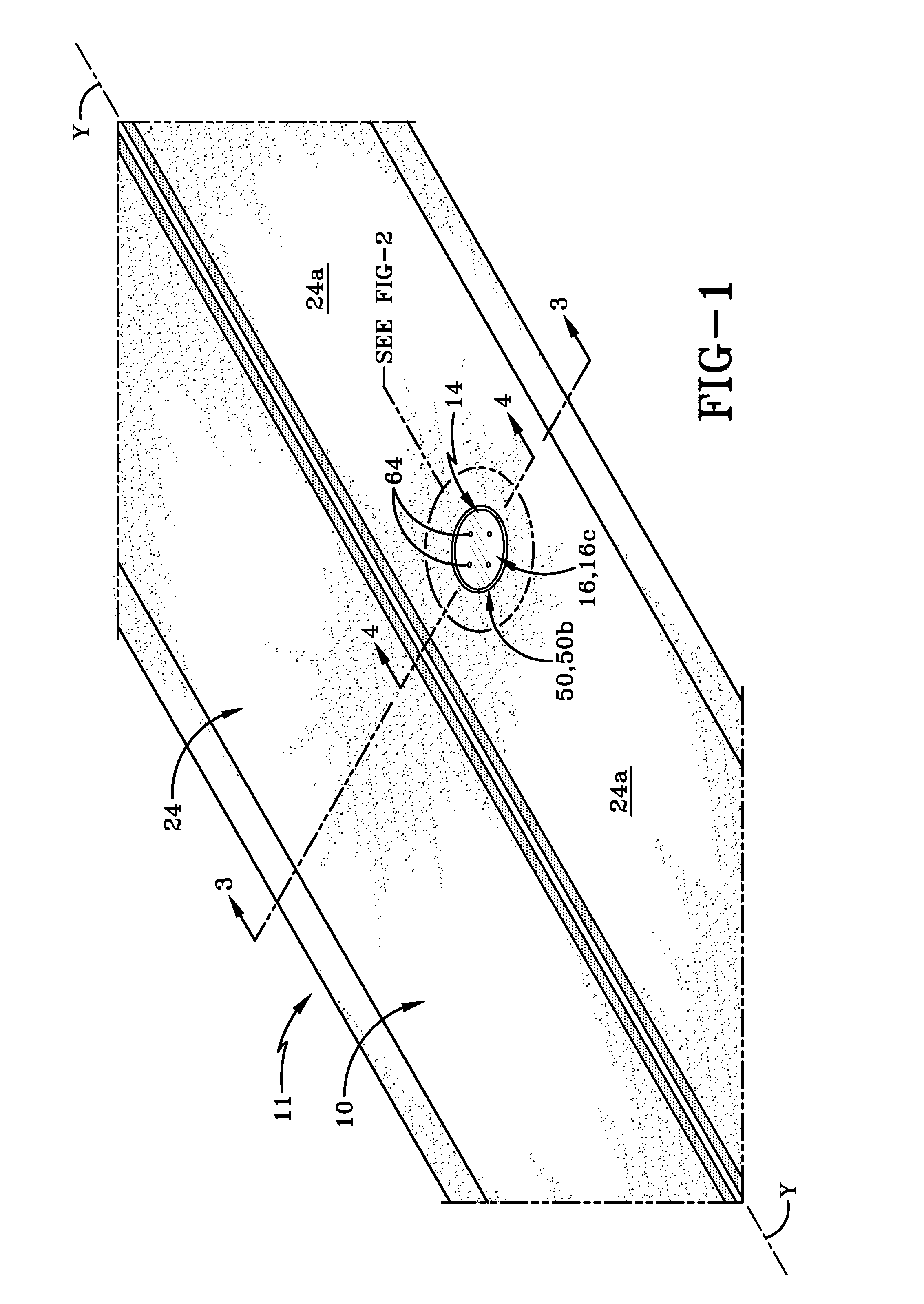
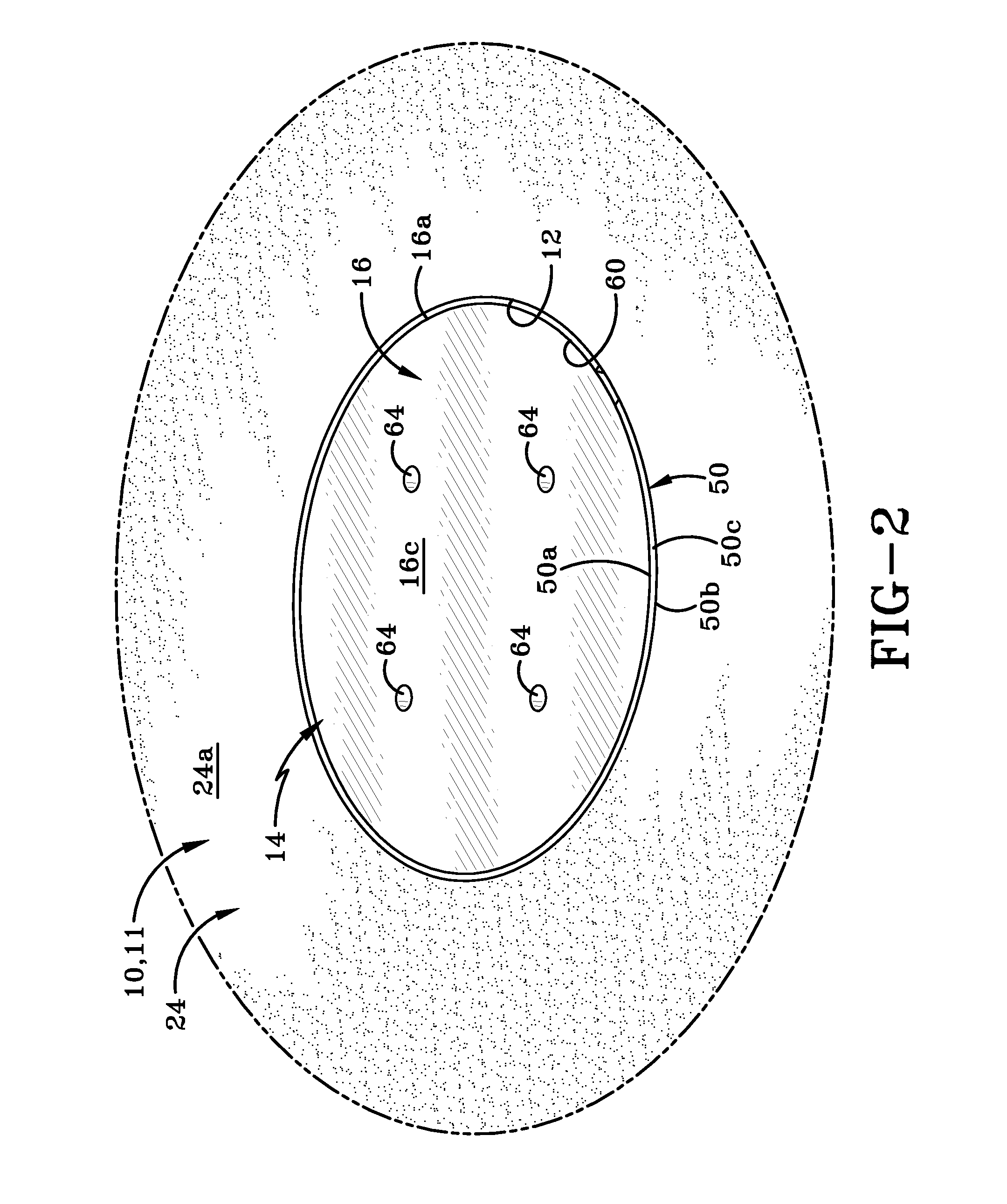
[0035]Referring to FIGS. 1 and 2, there is shown a paved surface or pavement 10 in which is defined an access hole 12 to a manhole assembly 14. A manhole cover 16 is engaged with manhole assembly 14 to close off access hole 12. Pavement 10 may be any type of surface including a road, a parking lot, a sidewalk etc. that includes a manhole assembly 14 and the paving material applied to pavement 10 may be asphalt, concrete or any other type of material that is applied in layers to form a rigid surface over which people and / or vehicles travel. In particular, the area of pavement 10 surrounding manhole assembly 14 is sloped in any one of a number of directions.

[0036]FIGS. 3 and 4 are cross-sections through pavement 10. FIG. 3 shows that manhole assembly 14 includes a manhole frame 28 disposed in a cavity 18 formed in a brick or masonry storm drain system 20 which is disposed beneath pavement 10. Pavement 10 comprises an original layer 22 of paving material and a new layer 24 of paving ma...


PUM


Abstract

A riser assembly and method for engaging the same to raise a manhole cover to be flush with an inclined paved surface after the application of an additional layer of paving material thereto. The riser assembly includes a first and second riser frame with a plurality of specially manufactured spacer blocks fixedly secured between them. The spacer blocks have progressively different height dimensions and sloped upper surfaces so as to create an angle between the first and second riser frames. The angle is complementary to the slope of the paved surface. The riser assembly includes an expansion device for adjusting the diameter of the second riser frame so that it frictionally engages the existing manhole frame. The fixed securement of the spacer blocks prevents relative movement between the first and second riser frames even when the diameter of the second riser frame is changed.

Description

BACKGROUND OF THE INVENTION[0001]1. Technical Field[0002]This invention relates generally to manhole cover supports. More particularly, this invention relates to a separate riser assembly that is placed within an existing manhole frame to raise the height of the manhole cover to compensate for added roadway pavement. Specifically, this invention is directed to a riser assembly for use with a manhole frame positioned on an incline. The riser assembly comprises a first riser frame and second riser frame having spacer blocks fixedly engaged between them in a manner that retains the first riser frame at an angle relative to the second riser frame. The inclined first riser frame supports the full circumference of the manhole cover at an angle complementary to the sloped road surface.[0003]2. Background Information[0004]Most underground facilities such as sanitary and storm sewers, utility conduits, and the like have manhole openings to provide access thereto. These manholes usually are l...

Claims


Application Information

Patent Timeline
IPC IPC(8): E02D29/14
CPCE02D29/14E02D29/1409
Inventor FIER, SCOTT D.
Owner AMERICAN HIGHWAY PRODS
Why Eureka
Try Eureka