
Prismatic secondary battery

Active Publication Date: 2013-08-01
SANYO ELECTRIC CO LTD
View PDF9 Cites 29 Cited by
  • Summary
  • Abstract
  • Description
  • Claims
  • Application Information

AI Technical Summary

Benefits of technology

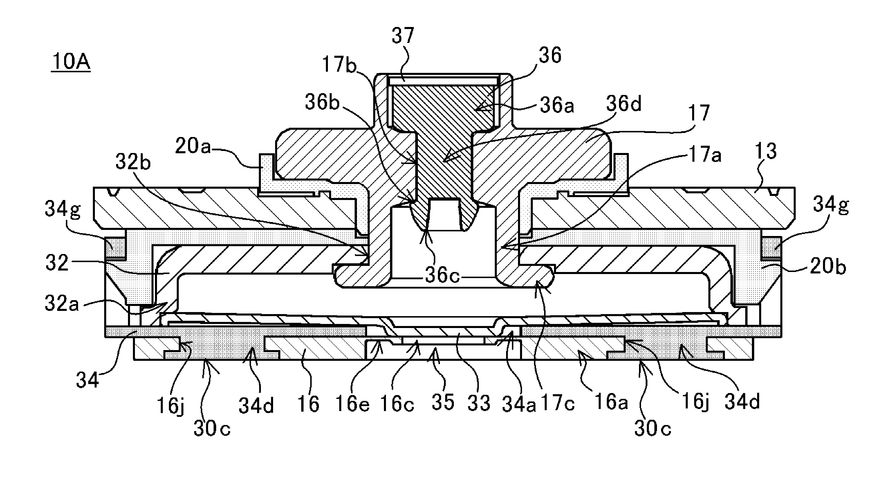
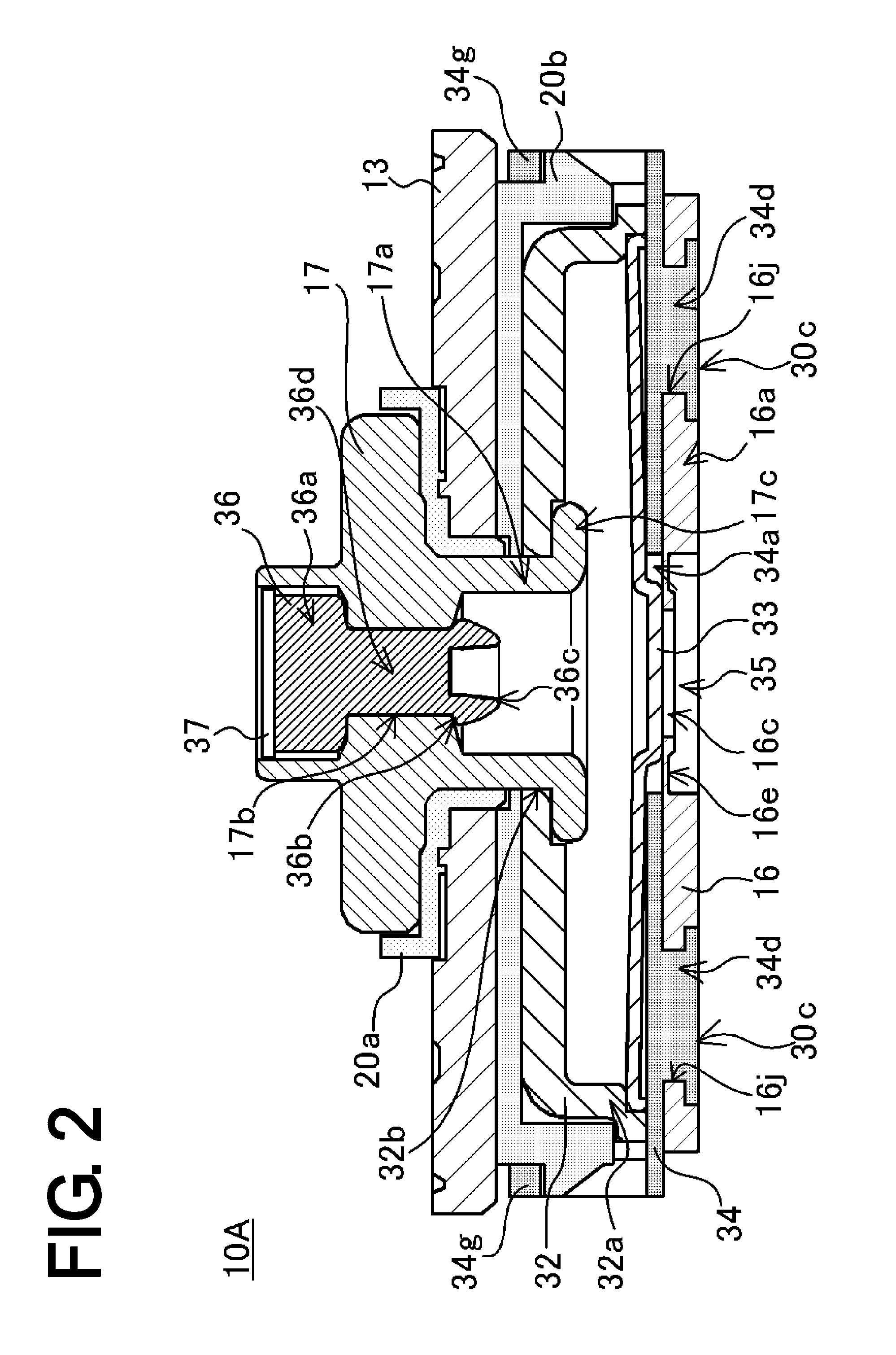
The invention provides a reliable prismatic secondary battery with a current interruption mechanism between the collector and external terminal. The mechanism is designed to prevent damage from shock and vibration.

Problems solved by technology

However, the electrode assembly may shift in the event that the battery is subjected to shock due to vibration, falling, etc.
Specifically, when the pressure inside the outer casing increases, the inversion plate is deformed, and then the connecting portion between the collector and the inversion plate, or the brittle portion of the thin portion, groove portion or similar provided in the collector, fractures.
Thus, the first region will be unlikely to be deformed even if the second regions of the collector are pulled due to the electrode assembly shifting in the event that the battery is subjected to shock as a result of vibration, falling, etc.
Thus, the first region will be unlikely to be deformed if the electrode assembly shifts in the event that the battery is subjected to shock due to vibration, falling, etc.
If electrolyte or cleaning fluid enters the through-hole, the current interruption mechanism could be corroded and consequently cease to operate normally.

Method used


Image

  • Prismatic secondary battery
  • Prismatic secondary battery
  • Prismatic secondary battery

Examples


first embodiment

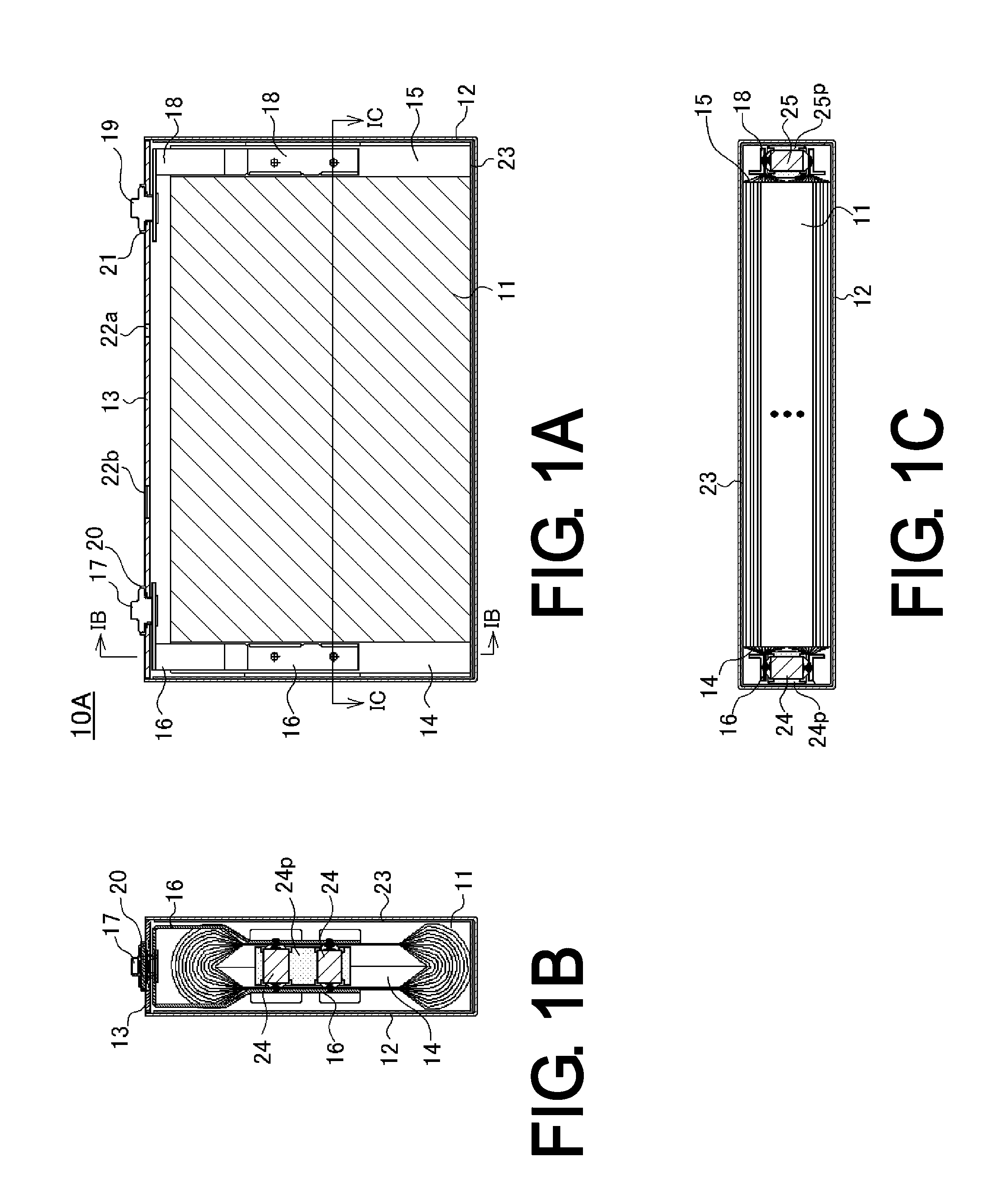
[0069]First, the prismatic nonaqueous electrolyte secondary battery of the first embodiment 1 will be described using FIGS. 1 to 5.

[0070]The prismatic nonaqueous electrolyte secondary battery 10A of the embodiment has a flattened wound electrode assembly 11 in which positive electrode plate and negative electrode plate are wound together with separators (all omitted from the drawings) interposed. To fabricate the positive electrode plate, a positive electrode active material mixture is spread over both sides of a positive electrode substrate of aluminum foil, and the resulting object is dried and rolled, then is slit at one end so that the aluminum foil is exposed in strips aligned in the lengthwise direction. To fabricate the negative electrode plate, a negative electrode active material mixture is spread over both sides of a negative electrode substrate of copper foil, and the resulting object is dried and rolled, then is slit at one end so that the copper foil is exposed in strip...

embodiment 2

[0102]The foregoing description of the prismatic nonaqueous electrolyte secondary battery 10A of Embodiment 1 sets forth an example where the first region 16a of the positive electrode collector 16 is wide, two second regions 16b are formed in mutually opposite positions with respect to the first region 16a, and two third fixing portions 30c are provided, one on each side in a direction perpendicular to the centerline c. However, there exist prismatic nonaqueous electrolyte secondary batteries that are narrow in width and have only one second region formed in a positive electrode collector. Thus, the prismatic nonaqueous electrolyte secondary battery 10B of Embodiment 2 is described below, using FIGS. 6 and 7, in which the first region 16a of the positive electrode collector 16 is narrow and only one second region 16b is formed.

[0103]FIG. 6A is an opened-out front view of the positive electrode collector of the prismatic nonaqueous electrolyte secondary battery of Embodiment 2, FIG....


PUM


Abstract

Disclosed is a highly reliable prismatic secondary battery with a current interruption mechanism that is unlikely to be damaged even if the battery is subjected to shock due to vibration, falling, etc. A second insulating member that has a through-hole is disposed between an inversion plate and the first region of a positive electrode collector, and through the through-hole the first region of the positive electrode collector is electrically connected to the inversion plate. First to third projections to formed around the through-hole formed in the second insulating member fit respectively into first to third openings formed in the first region of the positive electrode collector, and the diameters of their apexes are widened, thus forming first to third fixing portions. Thereby, the second insulating member is robustly joined to the first region of the positive electrode collector.

Description

TECHNICAL FIELD[0001]The present invention relates to a prismatic secondary battery, such as a nonaqueous electrolyte secondary battery or nickel-hydrogen secondary battery, that internally includes a current interruption mechanism.BACKGROUND ART[0002]As the drive power sources for portable electronic equipment such as mobile telephones (including smartphones), portable computers, PDAs, and portable music players, much use is made of alkaline secondary batteries and nonaqueous electrolyte secondary batteries, typified by nickel-hydrogen batteries and lithium ion batteries, respectively. Furthermore, alkaline secondary batteries and nonaqueous electrolyte secondary batteries are also much used as drive power sources for electric vehicles (EVs) and hybrid electric vehicles (HEVs, PHEVs), and in stationary storage battery systems in applications for curbing output variation of photovoltaic power generation and wind power generation, etc., in grid power peak load shifting applications f...

Claims


Application Information

Patent Timeline
IPC IPC(8): H01M2/34H01M2/12H01M50/176H01M50/528H01M50/538
CPCH01M2/0217H01M2/06H01M2/22H01M2/345H01M10/0431H01M2/12H01M2/263Y02E60/10H01M50/103H01M50/528H01M50/538H01M50/578Y02P70/50H01M50/176H01M50/30H01M2200/20
Inventor YOKOYAMA, YOSHINORIYAMAUCHI, YASUHIRONOHMA, TOSHIYUKI
Owner SANYO ELECTRIC CO LTD
Learn More