

Separator, Manufacturing Method Of The Same, And Electrochemical Device Having The Same
- Summary
- Abstract
- Description
- Claims
- Application Information
AI Technical Summary
Benefits of technology
Problems solved by technology
Method used
Image

Examples
example
Example 1
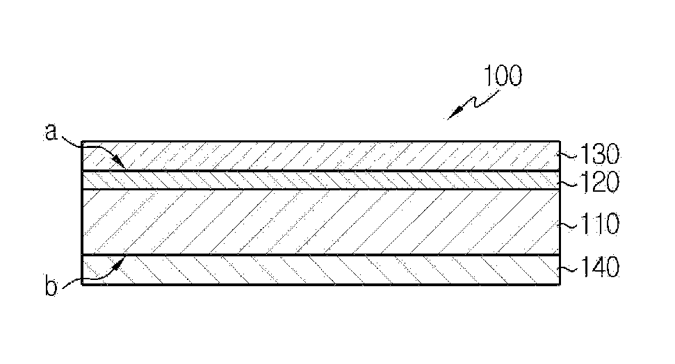
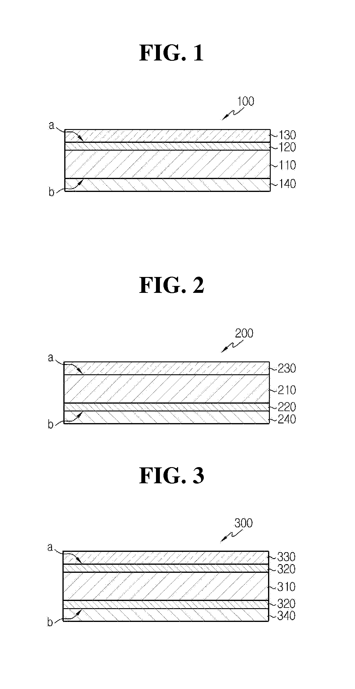
Manufacture of Separator Having Inorganic-Organic Coating Layer / Conductive Material-Comprised Active Material Coating Layer
[0086]Polyvinylidene fluoride-chlorotrifluoroethylene copolymer (PVdF-CTFE) and cyanoethylpullulan in a weight ratio of 10:2 were each added to acetone and dissolved at for about 12 hours to obtain a polymer solution. Al2O3 powders were added to the polymer solution until the weight ratio of polymer / inorganic particles reached 5 / 95, and then the inorganic particles were pulverized and dispersed by using a ball-mill method for 12 hours, to prepare a first slurry.
[0087]Also, to the polymer solution obtained above, LiFePO4 powders comprising a conductive material in an amount of 2% were added until the weight ratio of polymer / inorganic particles reached 10 / 90, and then the inorganic particles were pulverized and dispersed by using a ball-mill method for 12 hours, to prepare a second slurry.
[0088]In addition, to the polymer solution obtained above, LiTi2O4 ...
example 2
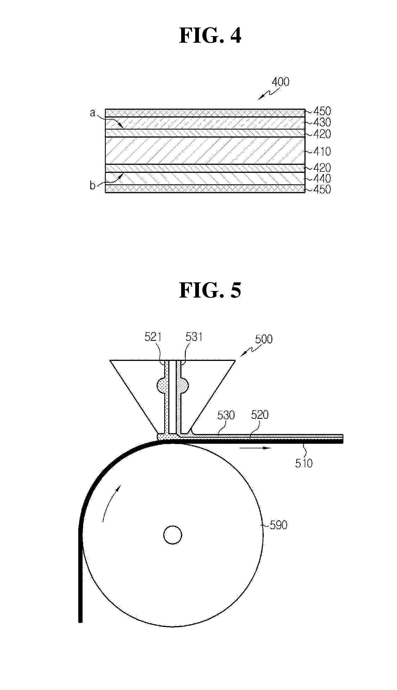
Manufacture of Separator Having Inorganic-Organic Coating Layer / Conductive Material-Comprised Active Material Coating Layer / Binder Polymer Layer
[0090]The procedures of Example 1 were repeated to prepare a separator, and then a solution of polyvinylidene fluoride-chlorotrifluoroethylene copolymer (PVdF-CTFE) was coated on both surfaces of the separator in a thickness of 3 μm by an electrospraying process, to obtain a separator having an electrode-separator adhesive layer.
example 3
Manufacture of Separator Having Inorganic-Organic Coating Layer / Conductive Material-Comprised Active Material Coating Layer / Binder Polymer Layer
[0091]The procedures of Example 1 were repeated except that the third slurry was not coated to prepare a separator, and then the same electrospraying process as Example 2 was carried out, to obtain a separator having an electrode-separator adhesive layer.
PUM
| Property | Measurement | Unit |
|---|---|---|
| Pore size | aaaaa | aaaaa |
| Thickness | aaaaa | aaaaa |
| Thickness | aaaaa | aaaaa |
Abstract
Description
Claims
Application Information