
Wireless power charging method and apparatus

a charging method and power technology, applied in the field of power charging system, can solve the problems of wasting power, reducing the required power, and wasting power, and achieve the effect of reducing power waste during charging

Inactive Publication Date: 2013-08-08
SAMSUNG ELECTRONICS CO LTD
View PDF3 Cites 58 Cited by
  • Summary
  • Abstract
  • Description
  • Claims
  • Application Information

AI Technical Summary

Benefits of technology

The present invention aims to minimize power wastage during wireless power charging. The technical effect of the patent text is to provide a solution for reducing power waste during wireless charging.

Problems solved by technology

However, when supplying power, the power supply device continuously transmits the same level of power until the object is fully charged, which often wastes power.
Specifically, the power supply device transmits an amount of power sufficient to charge a single device, even during the authentication and power transmission negotiation between the power supply device and the power receiving device, which wastes power.
Further, as a battery of a power receiving device is continually charged, the required power gradually reduces and a load of a source resonator increases, such that the power required by the power receiving device reduces.
However, in the existing wireless power charging systems, the power transmitted by the power supply device is not adjusted in accordance with the required power of the power receiving device, thereby wasting power.
Additionally, idle power will dissipate as heat at an amplifier of the power supply device, thereby wasting more power.

Method used


Image

  • Wireless power charging method and apparatus
  • Wireless power charging method and apparatus
  • Wireless power charging method and apparatus

Examples


Embodiment Construction

[0032]Various embodiments of the present invention will now be described in detail below with reference to the accompanying drawings. In the following description, specific details such as detailed configuration and components are provided to assist the overall understanding of certain embodiments of the present invention. Therefore, it should be apparent to those skilled in the art that various changes and modifications of the embodiments described herein can be made without departing from the scope and spirit of the present invention. In addition, descriptions of well-known functions and constructions are omitted for clarity and conciseness.

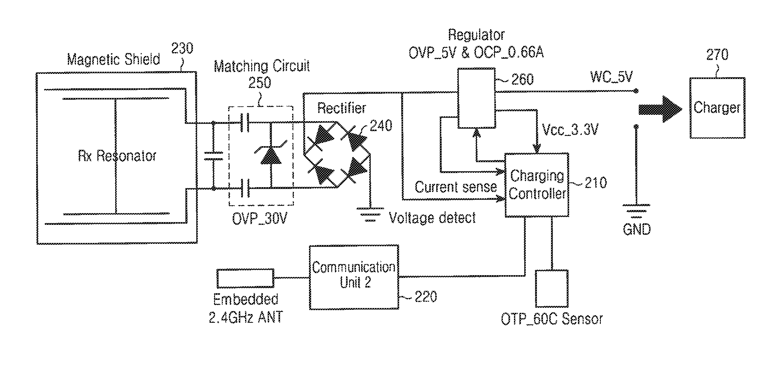
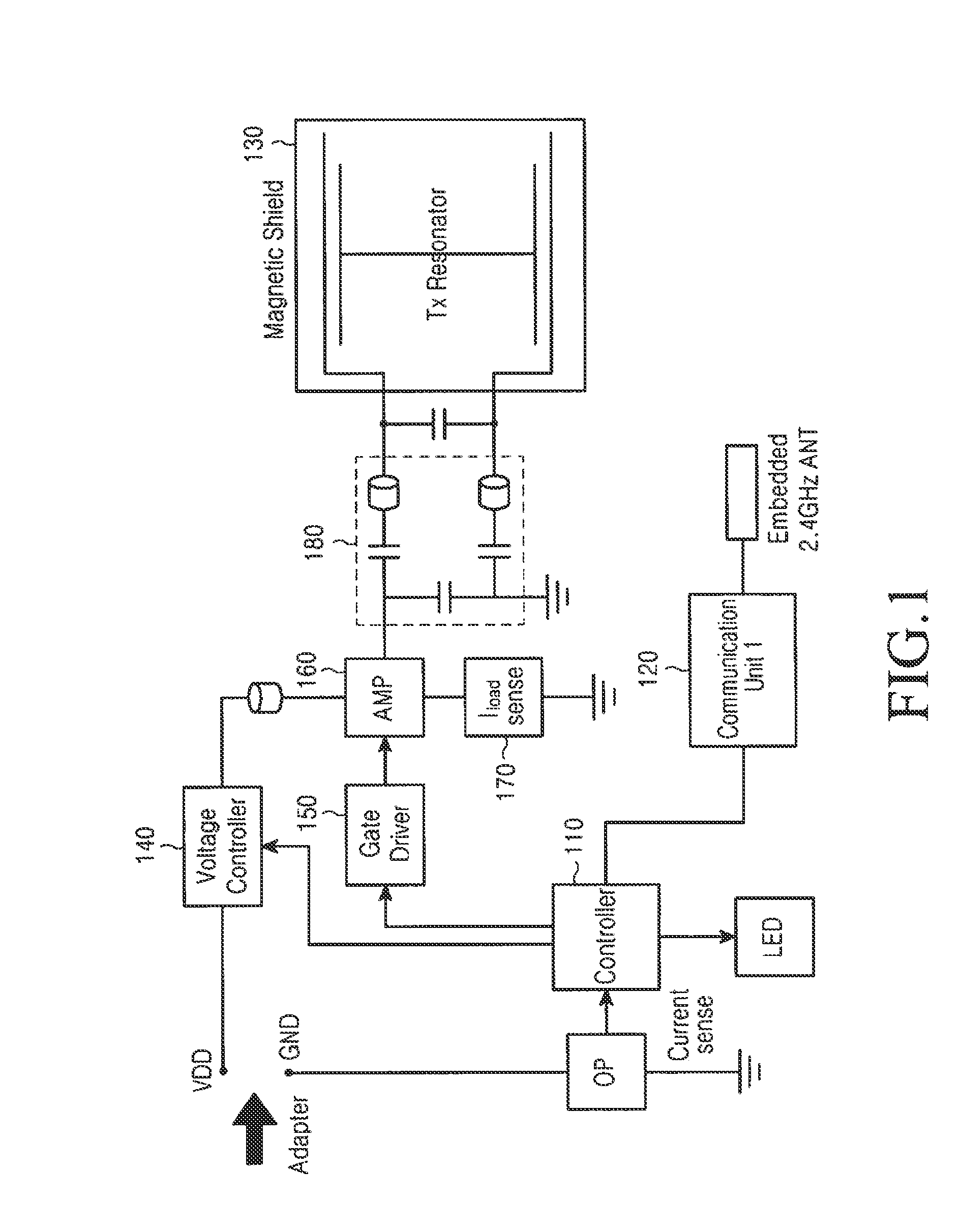
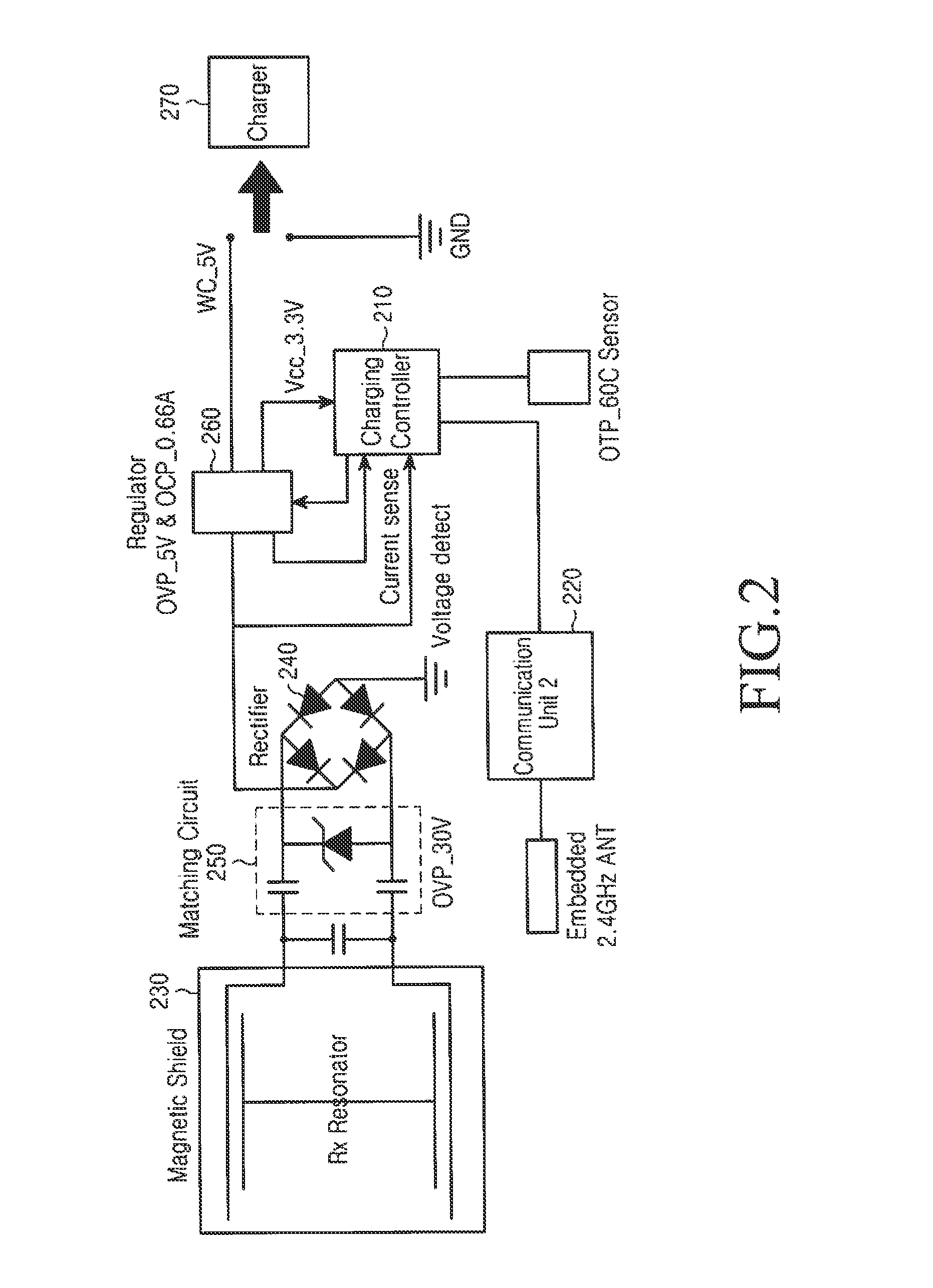
[0033]In accordance with an embodiment of the present invention, a method and apparatus are provided for wireless charging with minimized waste of power in a wireless power charging system, wherein a power supply device adjusts the amount of power supplied to a power receiving device, based on the charging process. More specifically, the power ...


PUM


Abstract

A method and apparatus are provided that efficiently perform wireless power charging. A power supply device checks an amount of charging power required by the power receiving device; determines a power level of the charging power that to be supplied over time, based on the amount of the charging power required by the power receiving device; transmits the charging power corresponding to the determined power level to the power receiving device; periodically receives a report message about a charging situation of the power receiving device from the power receiving device; calculates remaining required power, based on the report message received from the power receiving device; adjusts the determined power level depending on the calculated remaining power; and transmits the charging power corresponding to the adjusted power level to the power receiving device.

Description

PRIORITY[0001]This application claims priority under 35 U.S.C. §119(a) to Korean Patent Application Serial No. 10-2012-0012030, which was filed in the Korean Intellectual Property Office on Feb. 6, 2012, the entire disclosure of which is incorporated herein by reference.BACKGROUND OF THE INVENTION[0002]1. Field of the Invention[0003]The present invention relates generally to a power charging system, and more particularly, to a wireless power charging method and apparatus that efficiently charge a device.[0004]2. Description of the Related Art[0005]Wireless charging technologies wirelessly supply and receive power without a physical connector for power transfer. For example, a wireless charging technology includes an electromagnetic induction scheme that uses coils, a wireless power transmission scheme that delivers electrical energy by converting it into microwaves, or a resonance scheme.[0006]The electromagnetic induction scheme, which exchanges power between a primary coil and a s...

Claims


Application Information

Patent Timeline
Patent Type & Authority Applications(United States)
IPC IPC(8): H02J7/00H04B5/00
CPCH02J7/0042H02J7/0052H04B5/0037H04B5/0093H02J5/005H02J7/025H04B5/0075H02J7/00045H02J50/80H02J50/12H02J50/40H04B5/266H04B5/24H04B5/79H02J50/90
Inventor LEE, KYUNG-WOOBYUN, KANG-HOKIM, YU-SUYEO, SUNG-KU
Owner SAMSUNG ELECTRONICS CO LTD
Learn More