Stateless load balancer in a multi-node system for transparent processing with packet preservation

a load balancer and multi-node technology, applied in the field of distributed computing environment balancing workload distribution, can solve the problem that certain load balancers are provided as expensive front end devices

Inactive Publication Date: 2013-08-08
RADISYS CORP
View PDF0 Cites 187 Cited by
  • Summary
  • Abstract
  • Description
  • Claims
  • Application Information

AI Technical Summary

Problems solved by technology

Certain load balancers, however, are provided as expensive front end devices (e.g., external to the bladed system) or modify packet headers or other data in a way that may affect network addressing / routing or that may be detectable by other network elements or end users.

Method used


Image

  • Stateless load balancer in a multi-node system for transparent processing with packet preservation
  • Stateless load balancer in a multi-node system for transparent processing with packet preservation
  • Stateless load balancer in a multi-node system for transparent processing with packet preservation

Examples


Embodiment Construction

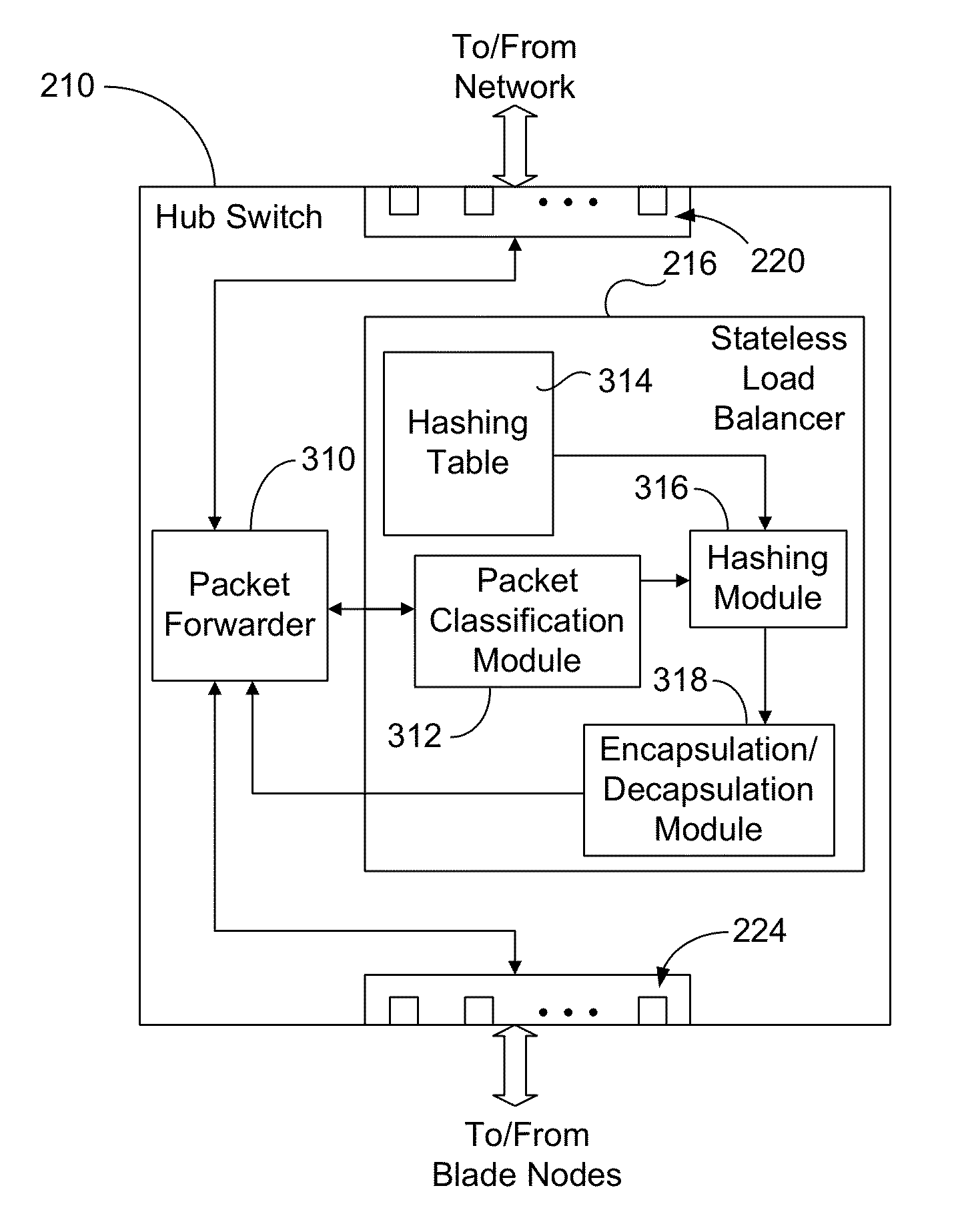
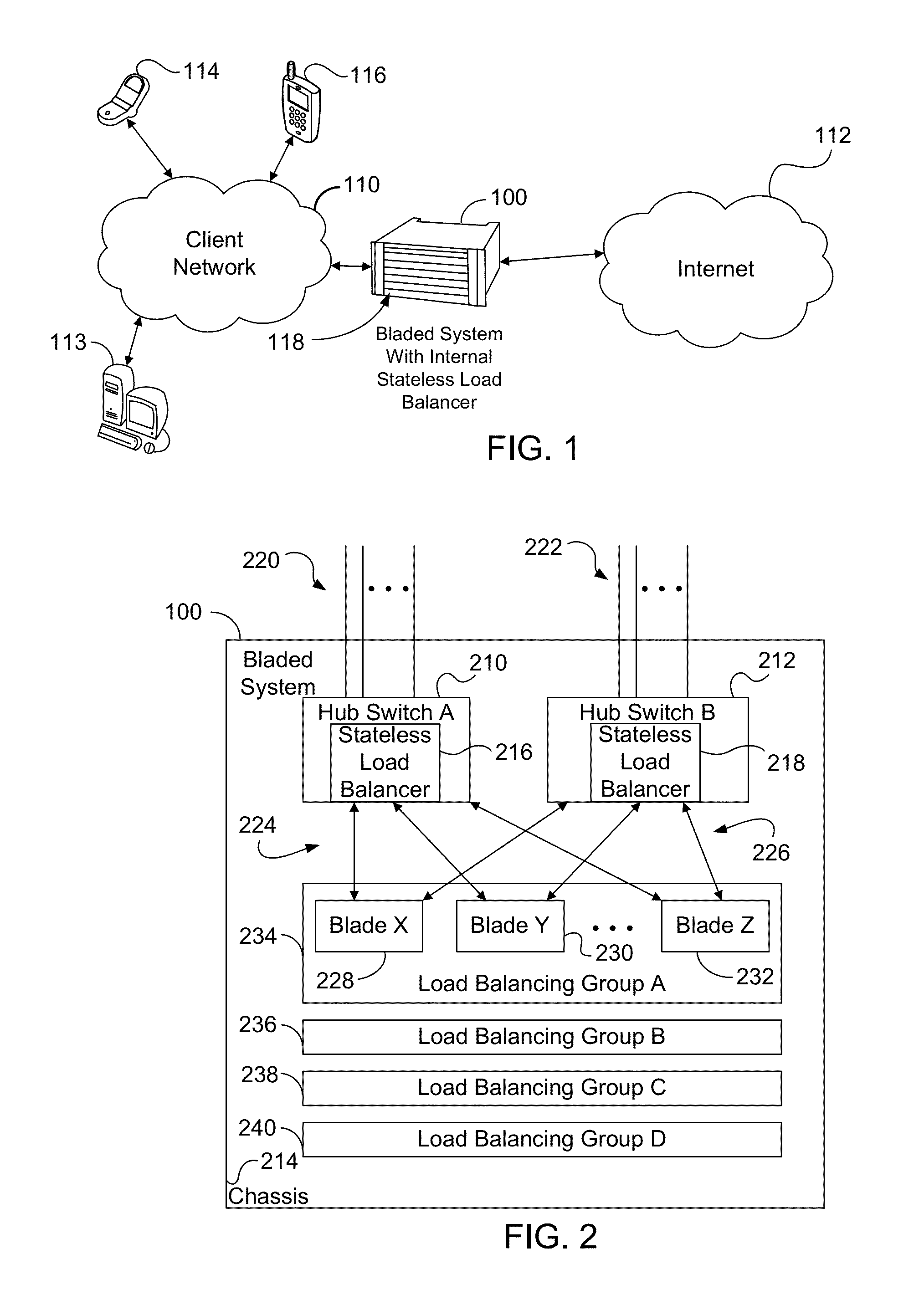
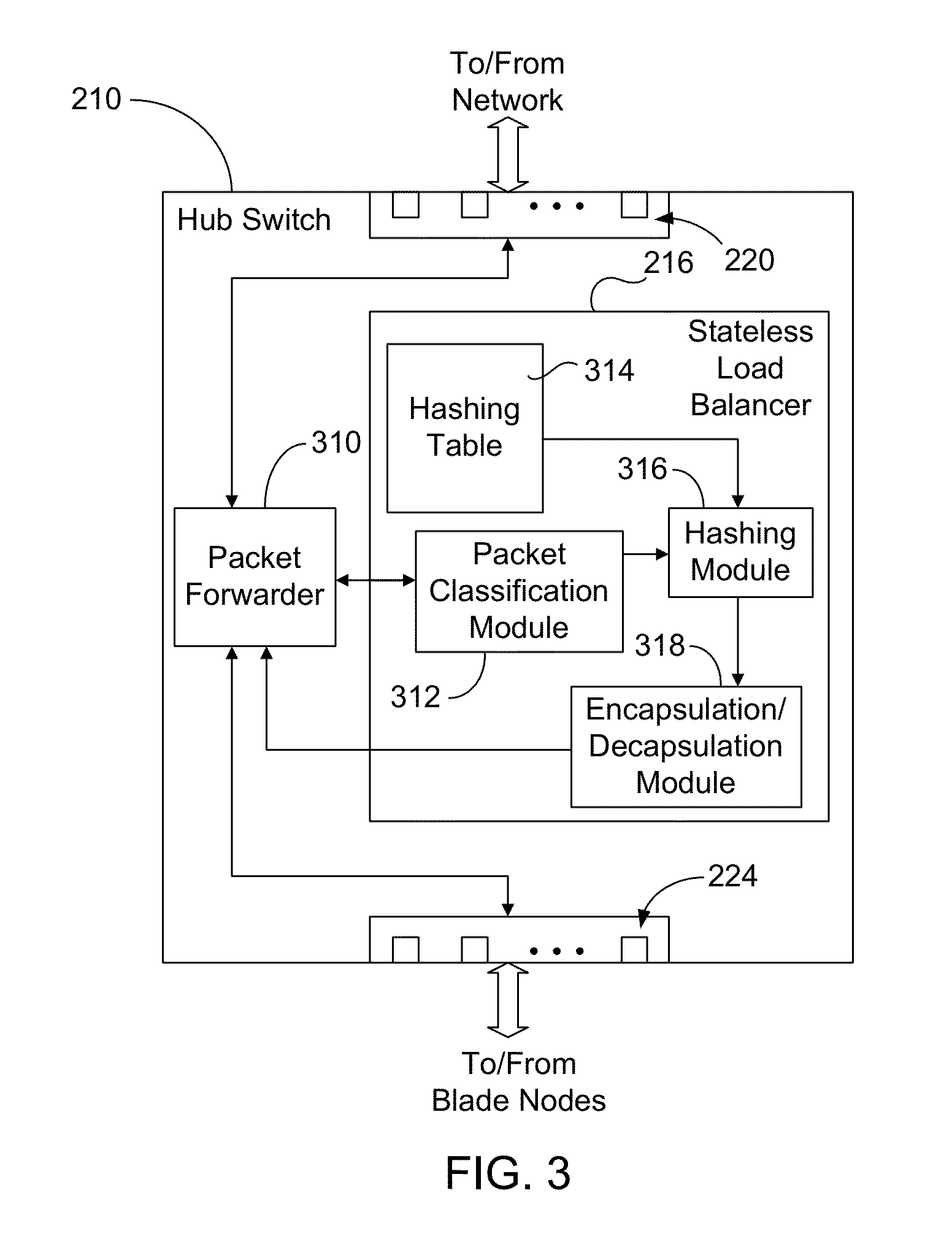
[0020]In certain embodiments disclosed herein, stateless load balancing is used to distribute network packets received by a distributed system across a set of processing resources within the system. As used herein, “stateless” is a broad term having its normal and customary meaning in the art and includes load balancing that considers each packet individually and independently, in a memoryless manner without considering previous decisions, yet is able to make consistent load balancing decisions to determine the processing resource for like packets. The load balancing is performed by the system's switching device, which reduces cost and complexity. In certain embodiments, the distributed system comprises a bladed system having, for example, an Ethernet backplane. The disclosed load distribution uses packet encapsulation to fully preserve the original packets for deep packet inspection or other bump-in-the-wire applications. Each original packet is encapsulated in another packet with ...


PUM


Abstract

Stateless load balancing of network packets within a system avoids detection by a network client or end user for deep packet inspection or other bump-in-the-wire applications. At least one header field of a received packet is used in generating a hash value. The hash value is used to identify a processing resource within the system for processing the received packet. Before being sent to the identified resource, the received packet is encapsulated with a new header that includes an indication of ingress port. The encapsulation does not modify the original packet. On a return path from the identified processing resource, the ingress port is determined from the encapsulated packet, the encapsulated packet is decapsulated to obtain a recovered packet that is identical to the received packet, and the recovered packet is forwarded to the network through an egress port as determined from the recovered ingress port.

Description

TECHNICAL FIELD[0001]This disclosure relates generally to balancing workload distribution in a distributed computing environment. In particular, this disclosure relates to methods, systems, and computer readable media for stateless load balancing of network traffic flows in multi-node systems for deep packet inspection or other applications where network transparency or idempotency is desired.BACKGROUND OF THE DISCLOSURE[0002]A bump-in-the wire architecture may be used for deep packet inspection where it may be desired to perform processing on packets in a manner that is not detectable by other network elements or end users, and in a manner that does not affect the addressing or routing of packets through the network. For example, law enforcement agencies may be authorized to intercept real time data carrying multimedia applications, such as voice or video, transmitted over the Internet without being detected by the call participants. Other deep packet inspection or bump-in-the-wire...

Claims


Application Information

Patent Timeline
Patent Type & Authority Applications(United States)
IPC IPC(8): H04L12/56H04L45/24
CPCH04L2212/0025H04L45/7453H04L47/825H04L47/125H04L45/72H04L45/24H04L2212/00
Inventor HU, MICHAEL W.ALLEMAN, ANDREW P.
Owner RADISYS CORP
Why Eureka
Try Eureka