Article Transport Facility

a technology for transporting facilities and articles, applied in the direction of conveyors, loading/unloading, storage devices, etc., can solve the problems of reducing the efficiency of transporting, affecting the installation location of article storage, and requiring additional time, so as to facilitate the maintenance work of operators and improve transporting efficiency. , the effect of reducing the time required to perform these operations

Active Publication Date: 2013-08-08
DAIFUKU CO LTD
View PDF5 Cites 64 Cited by
  • Summary
  • Abstract
  • Description
  • Claims
  • Application Information

AI Technical Summary

Benefits of technology

[0016]As such, since one of the first transport conveyer and the second transport conveyer is configured to function as the take-in portion while the other of the first transport conveyer and the second transport conveyer is configured to function as the take-out portion, the first transport conveyer may be provided to connect the first transfer position and a position inside the article storage while the second transport conveyer may be provided to connect the second transfer position and a position inside the article storage even if the article storage is installed at a location away from the travel rail in the lateral direction thereof. Therefore, articles may be delivered and received (i.e. transferred) between the article transport vehicle and article storage by providing the first transport conveyer and the second transport conveyer as a take-in portion and a take-out portion even when the article storage is located at any desired location without limiting the installation location of...

Problems solved by technology

The travel takes additional time, which leads to reduction in transporting efficiency.
However, in the facility described in Patent Document 2, because the storage unit of the article storage is used as the take-out portion (or take-in portion), the installation location of article storage is limited to a location close to the travel rail, such as a position located to a side of and close to the travel rail.
Therefore, the installation location for the article storage is ...

Method used


Image

  • Article Transport Facility
  • Article Transport Facility
  • Article Transport Facility

Examples


first embodiment

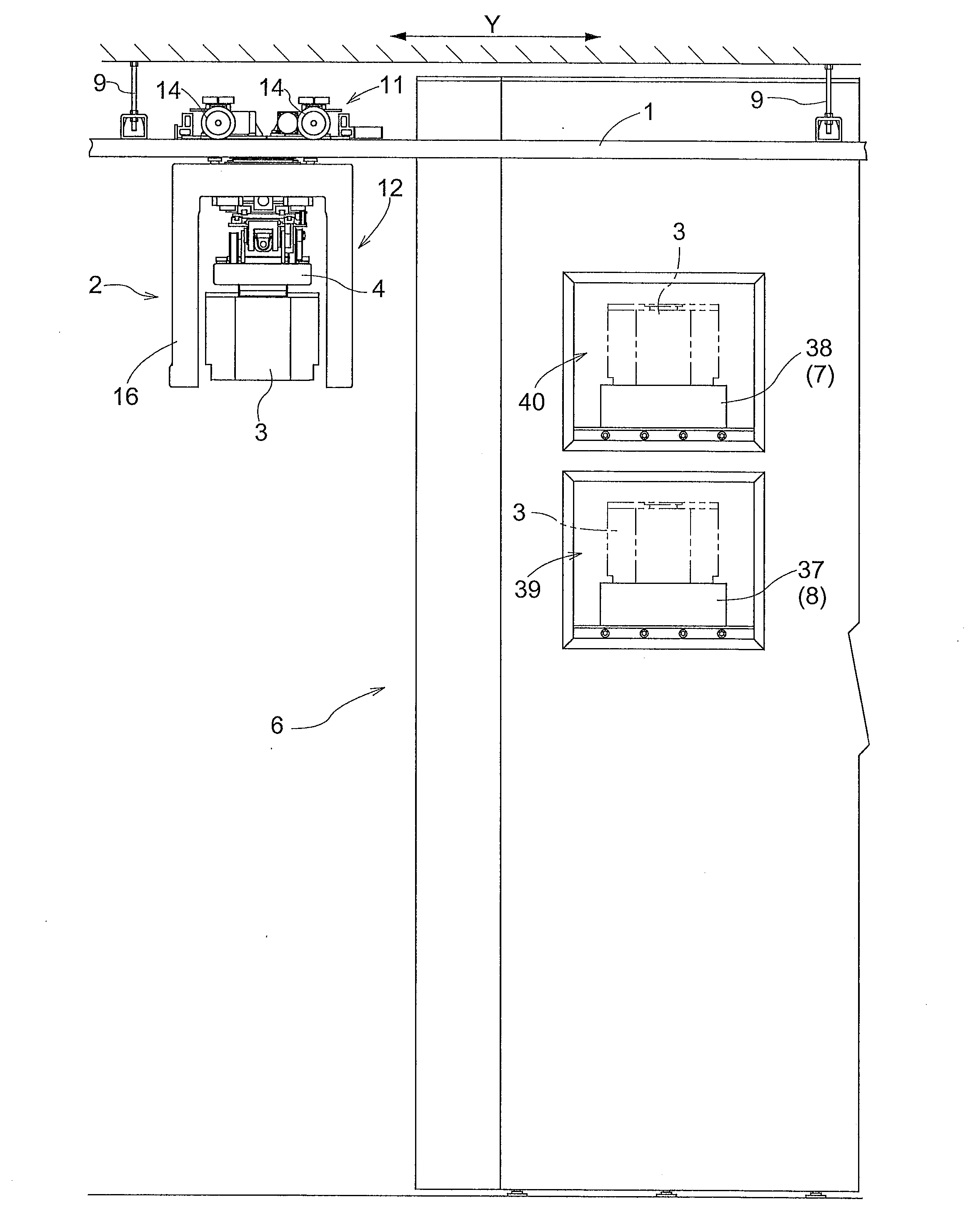
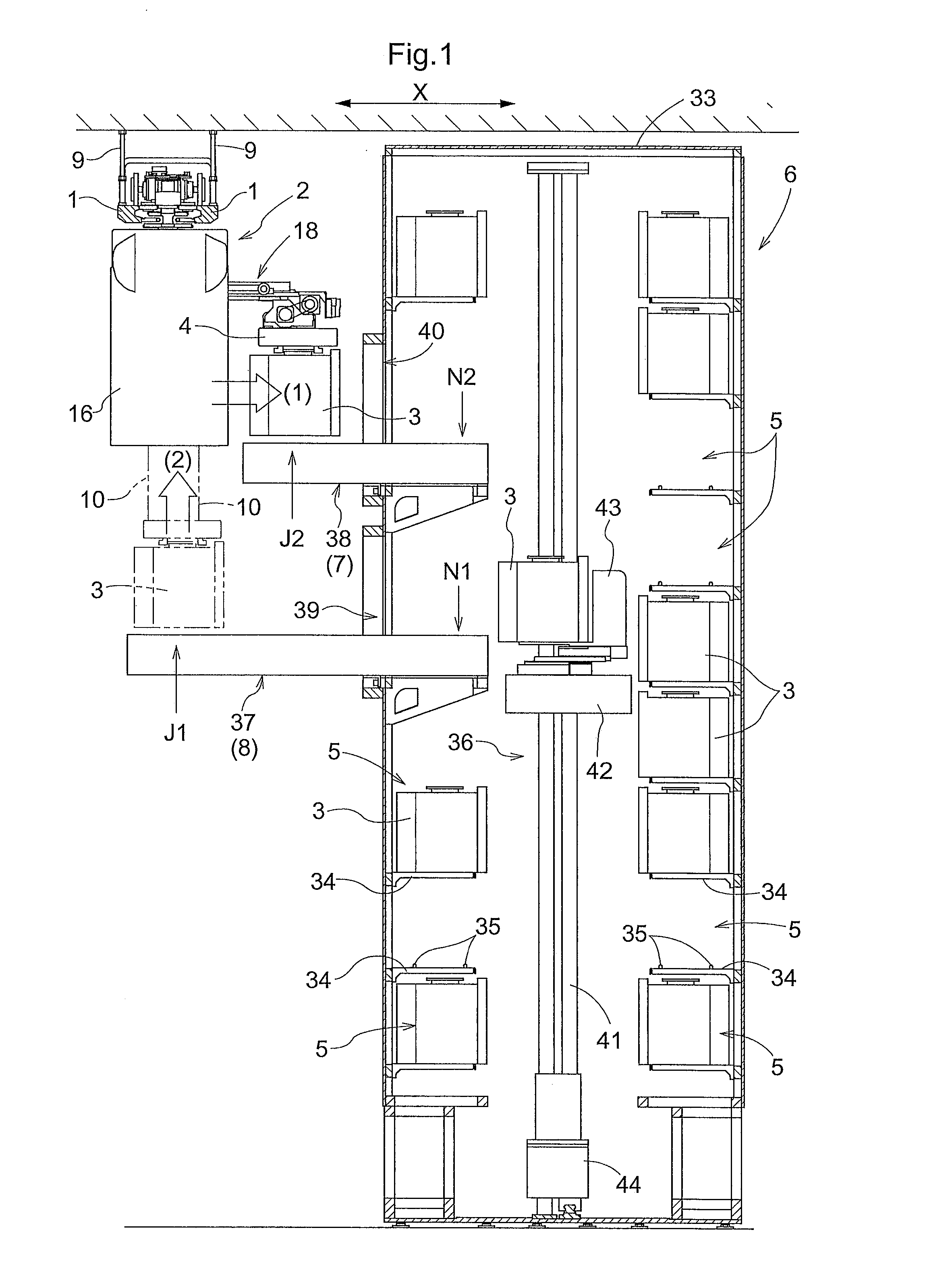
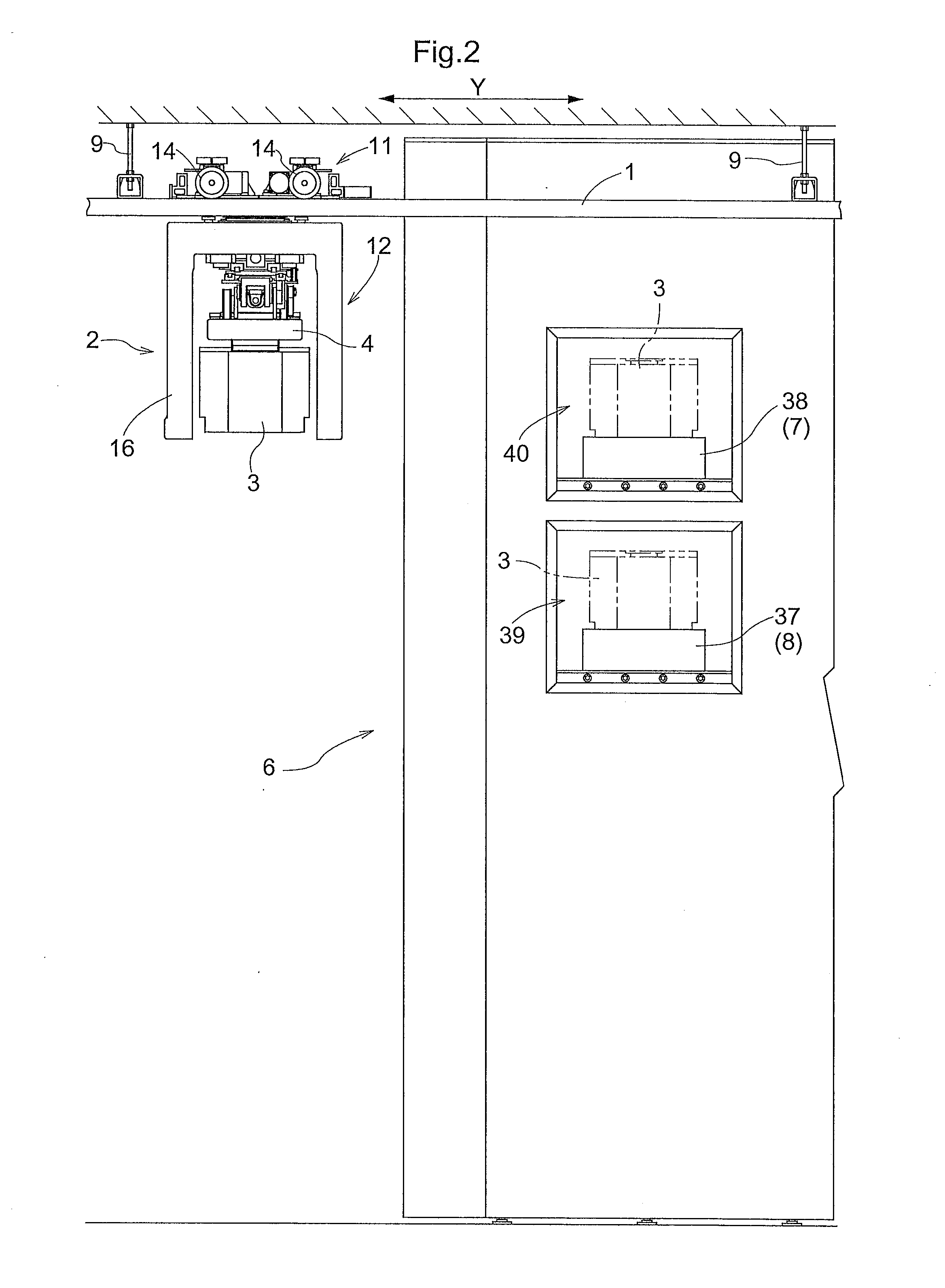
[0027]As shown in FIGS. 1 and 2, the article transport facility includes at least one article transport vehicle 2 which can or is configured to be able to travel along travel rails 1 that are provided on the ceiling side or supported by the ceiling. This article transport vehicle 2 transports an article 3 among a plurality of article processors (not shown) provided on the floor side. FIG. 1 shows a principal portion of the article transport facility as seen along the travel direction of the travel rails 1 (as seen along the direction Y in FIG. 2) whereas FIG. 2 shows the principal portion of the article transport facility as seen along the lateral direction of the travel rails 1 (as seen along the direction X in FIG. 1). Containers that hold semiconductor substrates are the article 3 to be transported in this article transport facility. And article processors perform various processes on the substrates in the articles. While not shown, the travel rails 1 extend along or by way of a ...

second embodiment

[0056]This second embodiment shown in FIG. 5 is an alternative embodiment for the take-in portion 7 and the take-out portion 8 described in the first embodiment described above and other parts are identical to those in the first embodiment. Accordingly, the description below focuses on the points that are different from the first embodiment. And the parts that are identical to those in the first embodiment bear the identical reference numerals and symbols as those in the first embodiment.

[0057]In the first embodiment above, the first transport conveyer 37 is configured to function as a take-out portion 8 whereas the second transport conveyer 38 is configured to function as a take-in portion 7. In contrast, in the second embodiment, the first transport conveyer 37 is configured to function as a take-in portion 7 whereas the second transport conveyer 38 is configured to function as a take-out portion 8, as shown in FIG. 5.

[0058]In this second embodiment, when the article transport veh...


PUM


Abstract

An article transport facility includes a first transport conveyer for transporting an article between a first transfer position outside the article storage and a position inside the article storage, and a second transport conveyer for transporting an article between a second transfer position outside the article storage and a position inside the article storage. An article transport vehicle is configured to be capable of transferring an article to or from one of the first transfer position and the second transfer position by vertically moving a grip portion with the article transport vehicle stopped at a transfer stop position in a path defined by a travel rail and is configured to be capable of transferring an article to or from the other of the first transfer position and the second transfer position by slidingly moving the grip portion with the article transport vehicle stopped at the transfer stop position.

Description

BACKGROUND OF THE INVENTION[0001]1. Field of the Invention[0002]The present invention relates to an article transport facility comprising an article transport vehicle that is capable of traveling along a travel rail provided on a ceiling side and an article storage including a plurality of storage units, the storage units being arranged in a vertical direction and being capable of storing articles that are transported by the article transport vehicle, wherein the article storage is located to a side of the travel rail in plan view and includes a take-in portion for receiving articles to be stored in the storage units from the article transport vehicle and a take-out portion for delivering articles to be retrieved from the storage units to the article transport vehicle.[0003]2. Description of the Related Art[0004]In article transport facilities such as one described above, a travel rail is provided on the ceiling side such that the rail extend by way of or along a plurality of articl...

Claims


Application Information

Patent Timeline
IPC IPC(8): B65G1/04
CPCH01L21/67733H01L21/67769B65G2201/0297B65G1/0407B65G1/0457
Inventor MORIMOTO, YUICHICHUMA, TAKESHI
Owner DAIFUKU CO LTD
Why Eureka
Try Eureka