Intraoral camera for dental chairs

a dental chair and intraoral camera technology, applied in the field of intraoral cameras, can solve the problems of limiting the usability of intraoral imaging devices, battery power must be maintained at high capacity, and not being practical in some environments

Active Publication Date: 2013-08-08
CARESTREAM DENTAL TECH TOPCO LTD
View PDF4 Cites 20 Cited by
  • Summary
  • Abstract
  • Description
  • Claims
  • Application Information

AI Technical Summary

Benefits of technology

[0007]An object of the present invention is to address the need for an improved intraoral imaging apparatus for the dental office environment. Embodiments of the present invention provide novel and convenient methods for providing power to an intraoral camera that is particularly well suited for use in an examination setting. Embodiments of the present invention take advantage of support power available through the dental chair and its associated utilities and adapt this power to meet the particular requirements of the intraoral camera.

Problems solved by technology

One problem with conventional intraoral imaging solutions relates to providing suitable power for the imaging camera and its support circuitry and obtaining the image data in an efficient manner.
Because of inherent difficulties in working around the patient and positioning the camera properly with a minimum of patient discomfort, using conventional arrangements of data and power cables can be awkward in practice and can limit the usability of the intra-oral imaging device.
However, in order to provide video images at a sufficient rate for near “real-time” response, battery power must be maintained at high capacity, which may not be practical for some environments.
Keeping a rechargeable battery well charged requires careful attention to detail on the part of the technician and is subject to human error or omission.

Method used


Image

  • Intraoral camera for dental chairs
  • Intraoral camera for dental chairs
  • Intraoral camera for dental chairs

Examples


Embodiment Construction

[0020]The following is a detailed description of the preferred embodiments of the invention, reference being made to the drawings in which the same reference numerals identify the same elements of structure in each of the several figures.

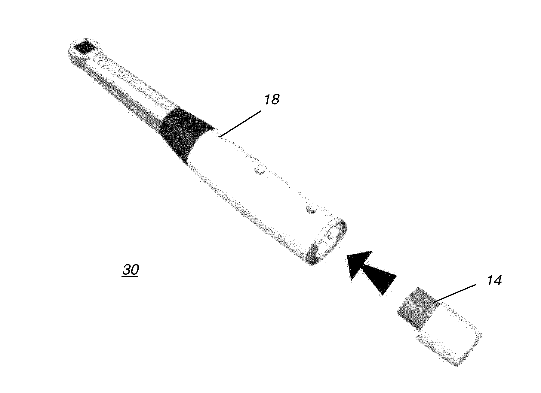
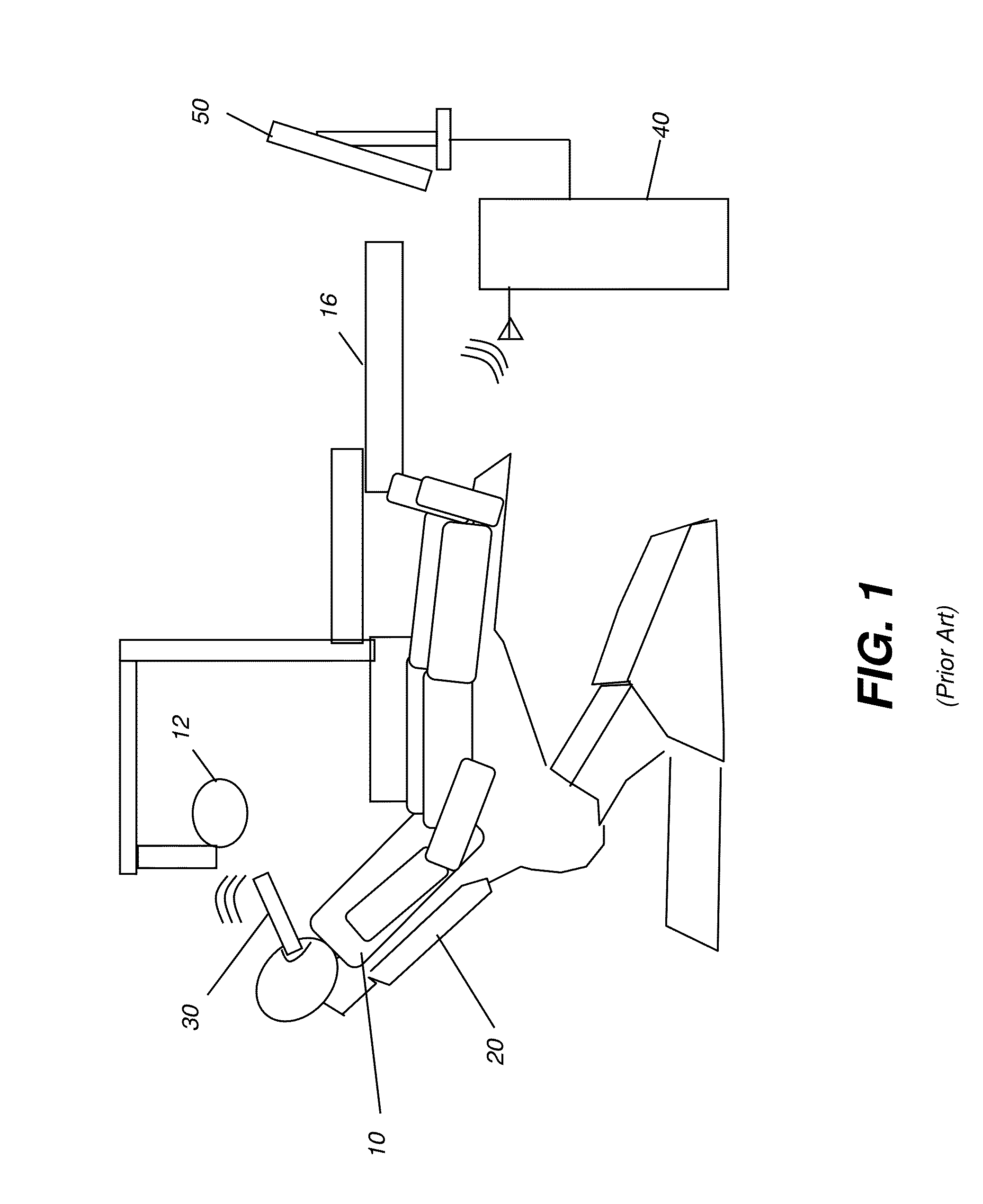
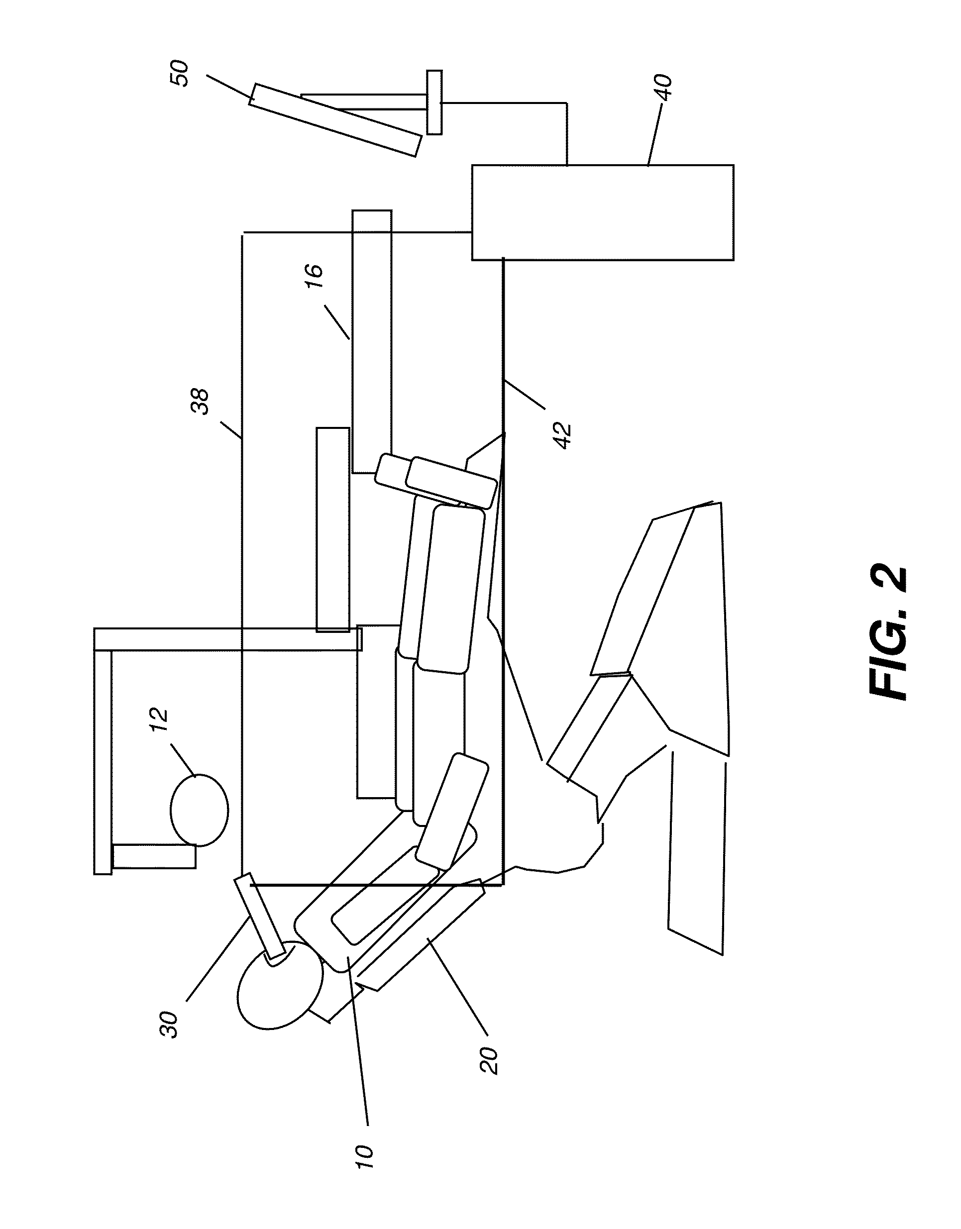
[0021]FIG. 1 shows an intraoral camera 30 providing wireless communication with a computer in a dental examination environment. Intraoral camera 30 is used to image a patient 10 in a dental chair 20. Image data is transmitted in a wireless manner to a computer 40 that is typically positioned in the near proximity of dental chair 20, with a display 50 for viewing the resulting video image that is obtained. Dental chair 20 is understood to comprise not only the seat on which the patient is positioned but typically also includes a number of support structures, such as a movable table 16, and a light 12, for example, and is often provided with a number of built-in electrical and plumbing components that serve in the examination process. A variable numbe...


PUM


Abstract

An intraoral camera comprising: an imaging section for obtaining image data from a patient in a dental chair; a transmitter comprising a transmitter configured for both wired and wireless transmission of the obtained image data to a computer; and a power section including a cable that obtains power from the dental chair or a battery module within the camera.

Description

CROSS REFERENCE TO RELATED APPLICATIONS[0001]This application claims priority to Provisional U.S. Patent Application Ser. No. 61 / 595,806, filed Feb. 7, 2012 in the names of Jean-Marc Inglese, et al., entitled INTRAORAL CAMERA FOR DENTAL CHAIRS, which is incorporated herein by reference in its entirety.FIELD OF THE INVENTION[0002]The invention relates generally to the field intraoral imaging and in particular to an intraoral camera adapted for use with the patient in the dental chair. More specifically, the invention relates to an intraoral digital camera that obtains its power from the dental chair and provides wireless transmission of images.BACKGROUND OF THE INVENTION[0003]Intraoral imaging is relied upon to provide useful information for the detection of caries and other dental conditions. A number of intraoral cameras have been developed for use by the dental practitioner or technologist, allowing an image of a patient's mouth to be readily obtained, displayed, and recorded.[000...

Claims


Application Information

Patent Timeline
Patent Type & Authority Applications(United States)
IPC IPC(8): A61B1/00
CPCA61B1/00011A61B1/00027A61B1/247A61B1/00036
Inventor INGLESE, JEAN-MARCSHELLARD, EDWARD R.
Owner CARESTREAM DENTAL TECH TOPCO LTD
Why Eureka
Try Eureka