Multiple vapor sources for vapor deposition

a vapor source and vapor deposition technology, applied in vacuum evaporation coating, mechanical equipment, valve construction details, etc., can solve the problems of not being able to form conformal thin films directly over high aspect ratio features, and not being able to uniformly deposit materials directly over high aspect ratio structures

Active Publication Date: 2013-08-08
ASM IP HLDG BV
View PDF49 Cites 331 Cited by
  • Summary
  • Abstract
  • Description
  • Claims
  • Application Information

AI Technical Summary

Problems solved by technology

In fact, typically less than a monolayer will form, due to steric hindrance by bulky source chemicals blocking possible reactive sites on the surface or due to limited number of reactive sites on the surface.
However, it is not straightforward to uniformly deposit materials directly over high aspect ratio structures in order to create thin films that meet certain specifications for a desired application.
ALD processes, similar to those described above, have yielded inconsistent results in forming conformal thin films directly over high aspect ratio features.
Schroeder hypothesized that the poor step coverage achieved from the use of HfCl4 and H2O was due to high or low sticking probability of the precursors.
Even some successful processes, such as ALD with precursors TEMAH and O3, have undesirable limitations.
However, these limitations on temperature have drawbacks.
Lowering the temperature of the precursor delivery system can reduce the efficiency of bubblers or vaporizers, and lowering the reactor temperature often results in lower quality films with more contaminants and higher leakage current.
Even for applications where the aspect ratio is not extreme, it can sometimes be challenging to supply vapor phase reactant consistently pulse after pulse (for ALD) or wafer after wafer (more generally), particularly where a high volume of the reactant is needed, such as when each wafer receives a very thick film and / or a very large surface needs to be coated.

Method used


Image

  • Multiple vapor sources for vapor deposition
  • Multiple vapor sources for vapor deposition
  • Multiple vapor sources for vapor deposition

Examples


example

[0087]As an example, reference is made to Verghese et al., ECS Conference, Los Angeles, Oct. 19, 2005, which describes an ALD process using precursors HfCl4 and H2O to form a thin film of HfO2 on a substrate without high aspect ratio features. The present inventors used source vessel C described in that publication to conduct an ALD process using these same precursors to deposit a thin film of HfO2 onto a substrate having high aspect ratio features. The source vessel C includes a series of stacked trays, which results in an enhanced exposed surface area. The carrier gas passes through each tray, resulting in continuous maximum pulse saturation. Experiments indicate that such a source design results in delivery of pulses that are substantially saturated with the metal precursor, in this case HfCl4, for the duration of the pulse.

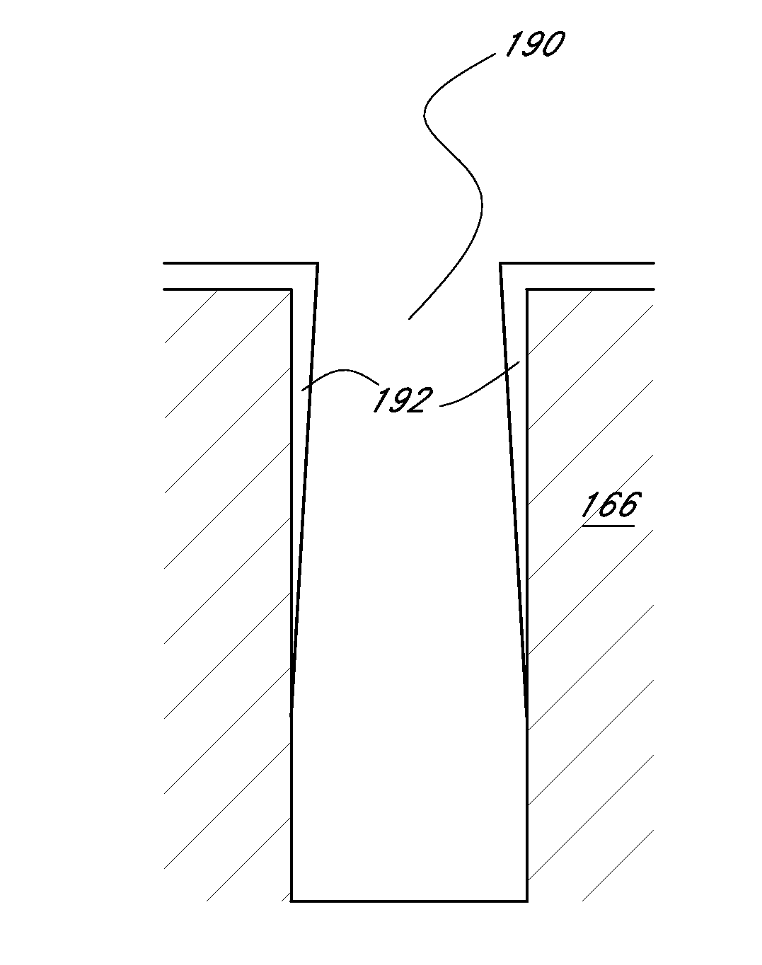
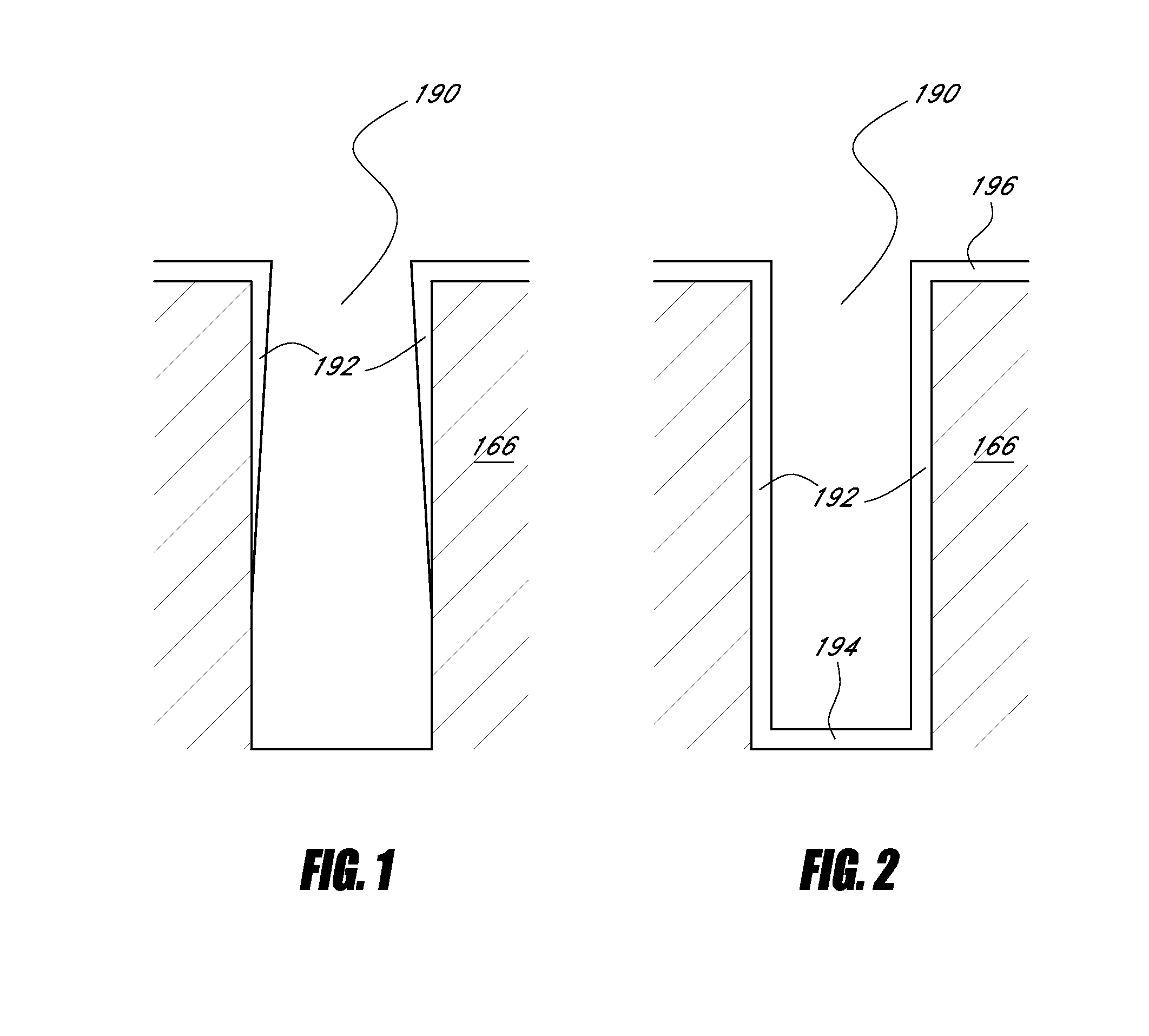
[0088]In this experiment using said source vessel C, conformal 20 nm HfO2 and HfSiO films were formed over high aspect ratio trench structures, including 0.11...


PUM

PropertyMeasurementUnit
temperatureaaaaaaaaaa

Abstract

A vapor deposition method and apparatus including at least two vessels containing a same first source chemical. A controller is programmed to simultaneously pulse to the reaction space doses or pulses of a gas from the vessels, each of the doses having a substantially consistent concentration of the first source chemical. The apparatus may also include at least two vessels containing a same second source chemical. The controller can be programmed to simultaneously pulse to the reaction space doses or pulses of a gas from the vessels containing the second source chemical, each of the doses having a substantially consistent concentration of the second source chemical. The second source chemical can be pulsed to the reaction space after the reaction space is purged of an excess of the first source chemical.

Description

BACKGROUND[0001]1. Field[0002]The present application relates generally to substrate fabrication and more particularly, to a method and apparatus for using multiple source chemical vessels to deliver the same source chemical in a vapor deposition process.[0003]2. Description of the Related Art[0004]In the fabrication of integrated circuits on substrates, such as semiconductor wafers, the vapor deposition of chemicals, such as chemical vapor deposition (“CVD”) and atomic layer deposition (“ALD”), is often desirable. The expansion of suitable source chemicals has increasingly led to the use of precursor materials that are naturally liquid or solid at room temperature and atmospheric pressures.[0005]Typically, an ALD process employs alternating surface reactions whereby a substrate on which deposition is to be conducted is maintained at a temperature above the condensation temperature for the vapor phase reactants and below the thermal decomposition temperatures. ALD is a chemically se...

Claims


Application Information

Patent Timeline
Patent Type & Authority Applications(United States)
IPC IPC(8): H01L21/314C23C16/52
CPCH01L21/02148H01L21/02181C23C16/45527C23C16/045C23C16/4482H01L21/0228H01J37/32449H01L21/3142H01L21/31645C23C14/246C23C16/4485C23C16/448C23C16/4486C23C16/45561F17C2270/0518C23C16/52F17C2205/0142F17C2205/0146H01L21/28194H10B12/038C23C16/45525H01L21/02172
Inventor POMAREDE, CHRISTOPHESHERO, ERICVERGHESE, MOHITHMAES, JAN WILLEMWANG, CHANG-GONG
Owner ASM IP HLDG BV
Why Eureka
Try Eureka