Blowout preventer and launcher sytem

a launcher and blowout prevention technology, applied in the field of blowout prevention, can solve the problem of complicated well intervention, and achieve the effect of high safety during deep sea intervention

Inactive Publication Date: 2013-08-15
WELLTEC AS
View PDF15 Cites 25 Cited by
  • Summary
  • Abstract
  • Description
  • Claims
  • Application Information

AI Technical Summary

Benefits of technology

[0010]It is an object of the present invention to wholly or partly overcome the above disadvantages and drawbacks of the prior a...

Problems solved by technology

When a well head is situated on the seabed on deep water, well intervention is more complicated since visibility below water can be poor.
Furthe...

Method used


Image

  • Blowout preventer and launcher sytem
  • Blowout preventer and launcher sytem
  • Blowout preventer and launcher sytem

Examples


Embodiment Construction

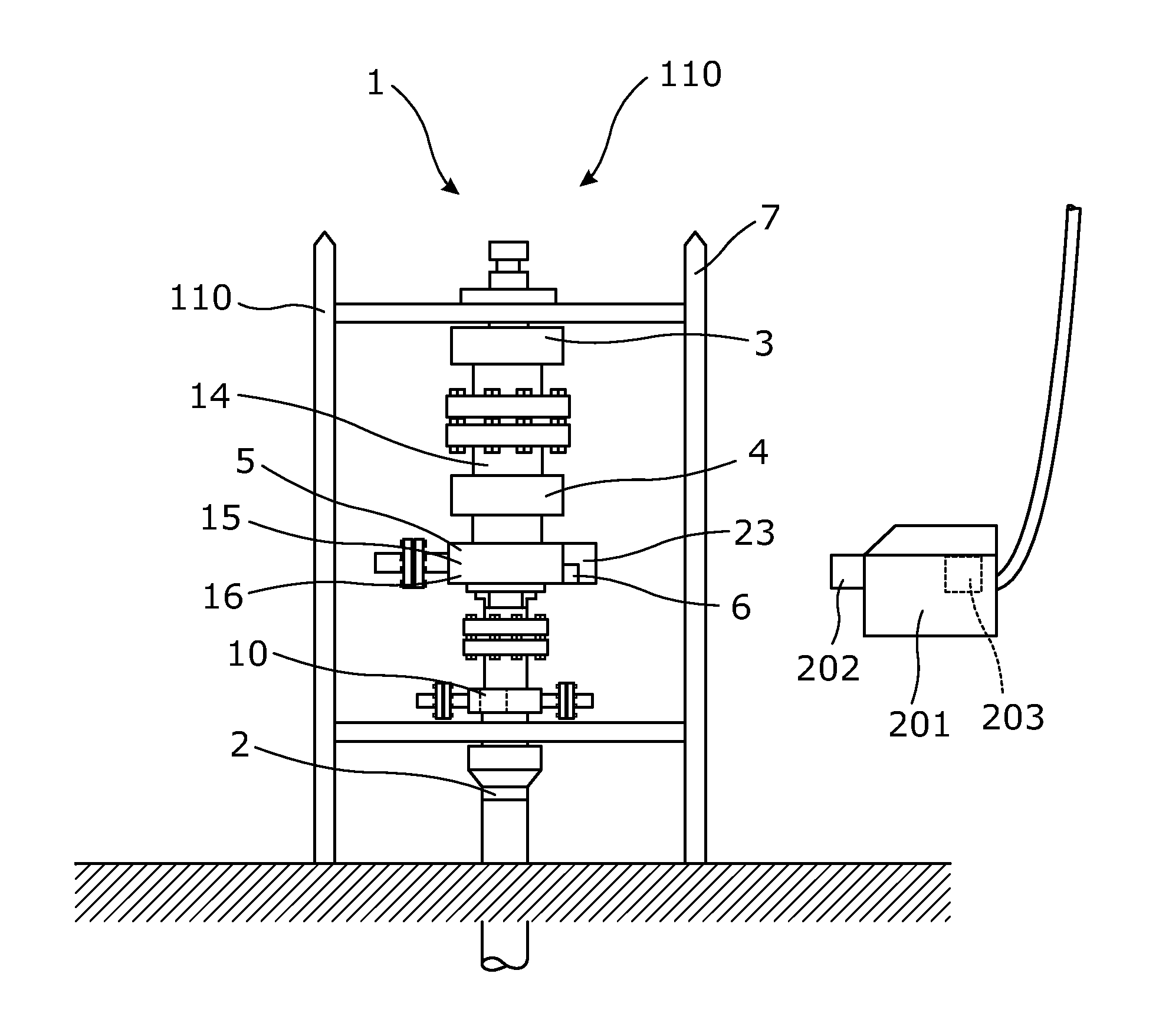
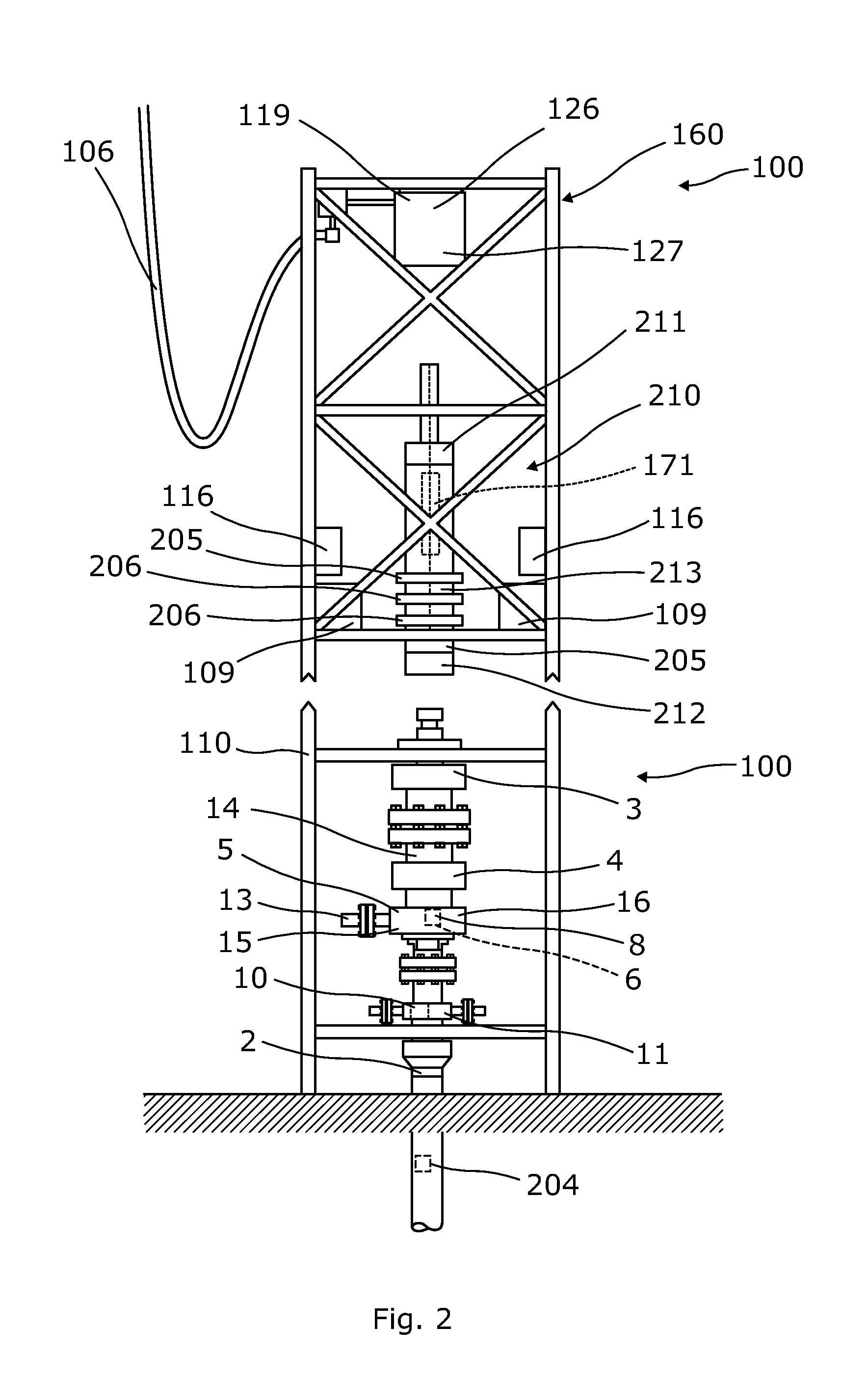
[0107]FIG. 1 shows a blowout preventer 1 mounted to a well head 2 arranged on the seabed on deep water. The blowout preventer 1 could also be mounted to a well head 2 arranged on-shore or terrestrially or to a well head arranged above water on a rig or vessel. In the following, the blowout preventer 1 will primarily be explained in relation to subsea well heads, but the invention is applicable to all types of well heads.

[0108]The blowout preventer 1 comprises a plurality of valves 3, 4 arranged on top of each other, and thus in fluid communication with each other. The first valve is an annular valve 3 and the rest of the valves are rams 4. The valves 3, 4 are connected and form part of a tubular pipe 14. In the end closest to the rams, the tubular pipe is connected with the well head 2, and in the other end, the tubular pipe may be connected with an intervention module 100.

[0109]The blowout preventer 1 is arranged in a supporting structure 110 in the form of a frame structure, and t...


PUM


Abstract

The present invention relates to a blowout preventer for being mounted on a well head, comprising a plurality of valves arranged in fluid communication with each other, connected and forming a tubular pipe. Furthermore, the invention relates to a launcher system, a well intervention module, a well intervention system and a well system.

Description

FIELD OF THE INVENTION[0001]The present invention relates to a blowout preventer for being mounted on a well head, comprising a plurality of valves arranged in fluid communication with each other, connected and forming a tubular pipe. Furthermore, the invention relates to a launcher system, a well intervention module, a well intervention system and a well system.BACKGROUND ART[0002]During production of oil, it may become necessary to perform maintenance work in a well or to open a production well. Such well work is known as well intervention. Inside the well, a production casing is placed which in its upper end is closed by a well head. The well head can be situated on land, on an oil rig or on the seabed below water.[0003]When a well head is situated on the seabed on deep water, well intervention is more complicated since visibility below water can be poor. Furthermore, the weather conditions at sea can interfere with the accomplishment of an intervention and, in case of a rough se...

Claims


Application Information

Patent Timeline
IPC IPC(8): E21B41/00E21B47/00E21B33/06E21B34/16E21B33/064
CPCE21B33/06E21B33/076E21B47/0001E21B34/16E21B41/0007E21B33/064Y10T137/8158E21B47/001
Inventor HALLUNDBAEK, JORGENMANGAL, LARS
Owner WELLTEC AS
Why Eureka
Try Eureka