Bone staple extrusion instrument and method of use and manufacturing

a technology of extrusion instruments and bone staples, applied in the field of bone staple extrusion instruments, can solve the problems of delayed or non-healing, affecting the use of surgeons, and requiring surgeons to manipulate implants

Active Publication Date: 2013-08-15
FOX WILLIAM CASEY
View PDF5 Cites 59 Cited by
  • Summary
  • Abstract
  • Description
  • Claims
  • Application Information

AI Technical Summary

Benefits of technology

[0030]McHarrie, U.S. Pat. No. 4,415,111 proposed a locator tube having a staple in a slot and a cooperating punch to push the staple from the tube into bone. McHarrie's invention cannot be used with shape changing staples because it does not constrain the staple legs from swinging in or the bridge from shortening. Consequently, the staples of this system do not change shape to pull together and compress bone. Pratt, U.S. Pat. No. 4,438,769, used a simple system to hold the staple bridge in a grasping driver that used a threaded coupler to lock the staple. This system supported the staple during hammer insertion into bone and through its geometry may urge bone together. The staple did not change shape to pull together and compress bone because the system required rigid staples to withstand the bone impaction forces.

Problems solved by technology

These designs cause the surgeon to need to manipulate the implant while trying to implant it in bone.
Thus these implants were difficult to implant or required complex expensive instruments thus impeding their use.
This gap can result in delayed or non-healing.
Consequently, with this impaired healing observation clinical demand for this type of bone staple has decreased.
These heat sensitive staples that rely on microstructure transition are problematic because during implantation the staple is in its mechanically soft martensitic state and commonly deform inappropriately with the impaction of surgical placement.
Furthermore, during shipping, costly strategies must be implemented to keep environmental heating from causing the staple to change shape prior to implantation.
Originally heat sensitive nitinol staples were activated with the temperature of the human body, approximately 37° C. This strategy and implant formulation caused critical issues by changing shape and applying bone fixation forces only after the surgical wound had been closed and allowed to warm to normal body temperature.
This post surgery shape change was reported to cause deformity and fracture.
This style of nitinol staple was further inconvenient in its use because the transition temperature began at below room temperature thus these implants were changing shape while being implanted by the surgeon.
Strategies such as keeping the staple on dry ice were used to partially overcome this issue but it added cost and the surgeon had to work quickly in procedures where deliberate and detailed technique was required.
The review of the prior art patent, technical and sales literature it is clear that the cost, inconvenience and risk of use of body temperature staples have impeded clinical adoption due to complications.
Though Fox's, U.S. Pat. No. 7,240,677 elevated temperature staple heating strategies have seen extensive clinical use, this style and the body temperature heated implants are deficient due to variation in bone fixation force due to environmental heating or cooling and are soft in their mechanical properties during implantation.
These issues and the requirement to have dry ice or an electrical bipolar heating unit have limited the clinical adoption of elevated temperature staples.
The clinical use of the Mohr staple has been long discontinued due to difficulty in stretching the bridge during placement and the frequency of having the staple unexpectedly released from the hook and spring from the surgical field.
This is a sufficient deficiency because, the hand deforming is not precise, the staple must be sterile and made cold before deforming and the implant is soft when implanted and thus may bend with the impaction of placement in bone.
The simultaneous requirement for the surgeon to open the staple legs and insert the implant into bone is surgically difficult in many procedures, and for the other reasons noted above, have limited the clinical use of this implant.
Consequently, in use these implants have significant disadvantages compared to the embodiments of the subject invention.
The instrument was complex, expensive and in aged porous bone sometimes caused bone fracture during staple insertion.
These staples do not store mechanical energy or change shape and thus the staples of his system cannot pull together and compress bone.
The convenience of these systems is overcome by the high cost, complicated design of the staple gun, and difficulty in cleaning and sterilizing the stapler for repeated patient use.

Method used


Image

  • Bone staple extrusion instrument and method of use and manufacturing
  • Bone staple extrusion instrument and method of use and manufacturing
  • Bone staple extrusion instrument and method of use and manufacturing

Examples


Embodiment Construction

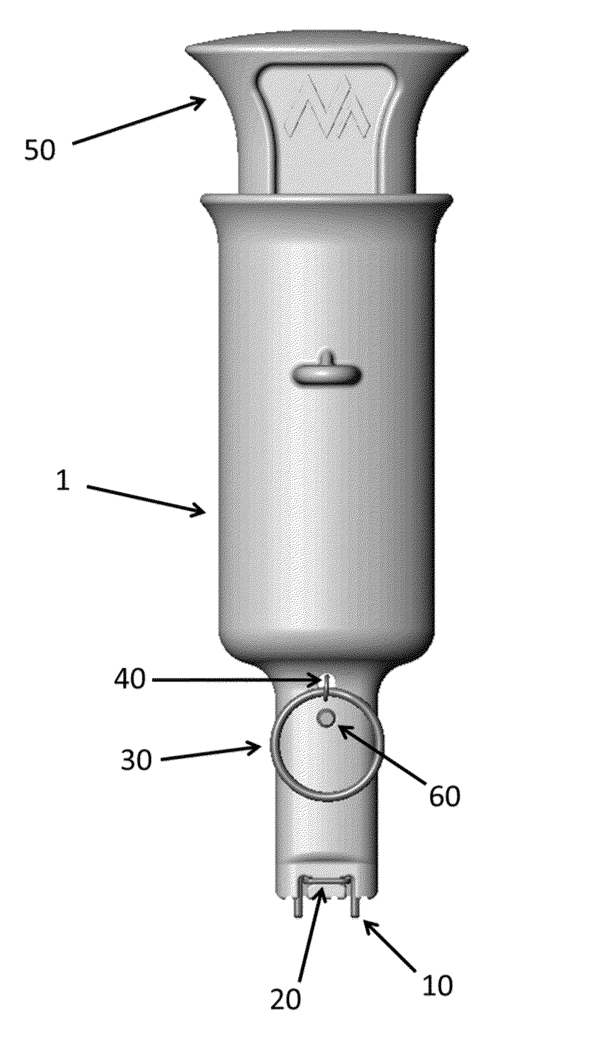
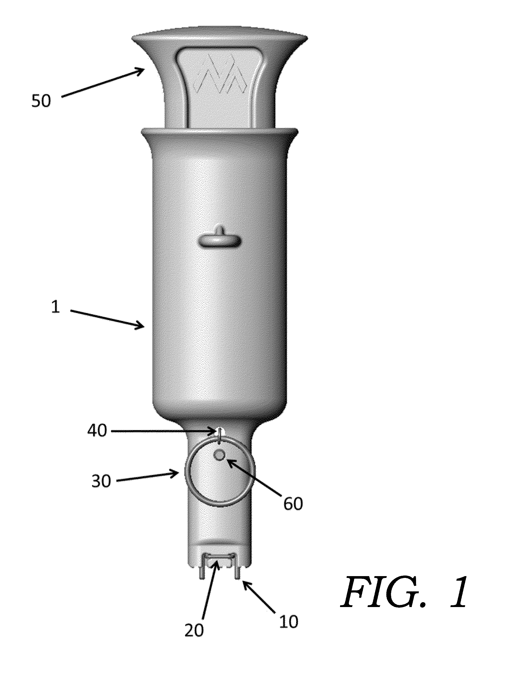
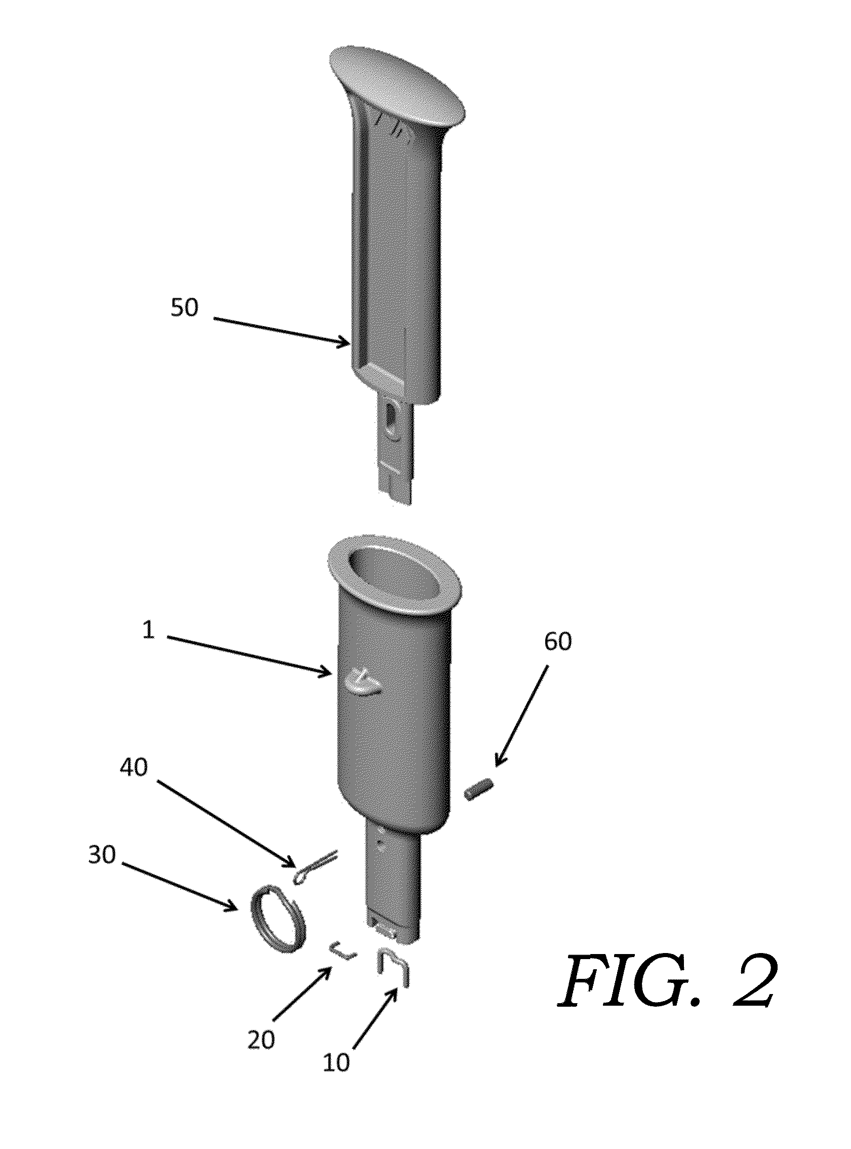
[0102]The embodiments of the subject invention are staple extrusion instruments (or bone staple extrusion instruments) that are each utilized for retaining and then implanting a staple with a plurality of legs, commonly in a U- or table-shaped configuration where the U-shaped has two legs and the table-shaped has three or more legs. All staple styles independent of the number of legs have a bridge that joins the plurality of legs. The particular staple extrusion instrument is designed to receive and restrain a corresponding configuration of the staple that is to be retained and implanted using that staple extrusion instrument.

Staples

[0103]As discussed and described herein, embodiments of the present inventions include staple extrusion instruments and methods of use to implant staples in which the staples are able to move between two shapes. Generally, one shape is a “parallel” shape, and the other shape is a “non-parallel” shape. A staple has a “parallel” shape when the legs of the ...


PUM

PropertyMeasurementUnit
transition temperatureaaaaaaaaaa
temperaturesaaaaaaaaaa

Abstract

A bone staple extrusion instruments used for fixation of bone and soft tissue of the musculoskeletal system and the methods for their use and manufacture. The bone staple extrusion instruments are used for insertion of staples into bones, which staples change shape through their metallurgic properties and the release from the bone staple extrusion instruments. In some embodiments, the bone staples pull together and compress bone once released from the bone staple extrusion instruments. In other embodiments, the staples push outward to place the bones in tension once released from the bone staple extrusion instrument.

Description

CROSS-REFERENCE TO RELATED PATENT APPLICATIONS[0001]This application claims priority to U.S. Patent Appl. Ser. No. 61 / 759,327, filed Jan. 31, 2013, entitled “Bone Staple Extrusion Instrument and Method of Use and Manufacturing.” This application further claims priority to: (a) U.S. patent application Ser. No. 13 / 192,162; (b) U.S. patent application Ser. No. 13 / 192,177; (c) U.S. patent application Ser. No. 13 / 192,186; and (d) U.S. patent application Ser. No. 13 / 192,198. Each of the foregoing patent applications was filed on Jul. 27, 2011, is entitled “Bone Staple, Instrument and Method of Use And Manufacturing,” and is commonly owned by the owner of the present invention. This application further claims priority to International Patent Application No. PCT / US12 / 48,539, filed on Jul. 27, 2012, entitled “Bone Staple, Instrument and Method of Use And Manufacturing” (the “PCT '539 patent Application”). The foregoing patent applications are hereby incorporated herein by reference in their ...

Claims


Application Information

Patent Timeline
Patent Type & Authority Applications(United States)
IPC IPC(8): A61B17/068
CPCA61B17/0682A61B17/0642A61B2019/0278A61B19/0271A61B2017/00867A61B19/026A61B17/0644A61B17/0684A61B2017/0023A61B2017/0645A61B50/30A61B50/33A61B2050/3008
Inventor FOX, WILLIAM CASEY
Owner FOX WILLIAM CASEY
Why Eureka
Try Eureka