Structure of front section of vehicle body

Active Publication Date: 2013-08-15
HONDA MOTOR CO LTD
View PDF6 Cites 23 Cited by
  • Summary
  • Abstract
  • Description
  • Claims
  • Application Information

AI Technical Summary

Benefits of technology

The invention is about a vehicle design that reduces the length of the engine compartment to create a short overhang and increases the impact-absorbing capacity of the vehicle without adding much weight. By adding impact-absorbing members to the front side frames and front bulk head, the area where light collisions can be counteracted is increased. This design also ensures a strong connection between the front side frames and front bulk head, improves the load transfer during front collisions, and reduces the impact on the front ends during crashes. Additionally, a closed cross-section shape is used for the side stays, which increases the efficiency of load transfer and improves the connection rigidity between the front side frames and upper frames. Overall, this design improves the vehicle's ability to absorb and manage light collisions, reducing damage to the vehicle and ensuring safety during crashes.

Problems solved by technology

This connected section is a connected section between front and rear members (front side frames) and left and right members (the front bulk head) forming the engine compartment, and the vehicle body may lose handling stability and torsional rigidity due to a decrease in the connecting rigidity.

Method used


Image

  • Structure of front section of vehicle body
  • Structure of front section of vehicle body
  • Structure of front section of vehicle body

Examples


embodiment 1

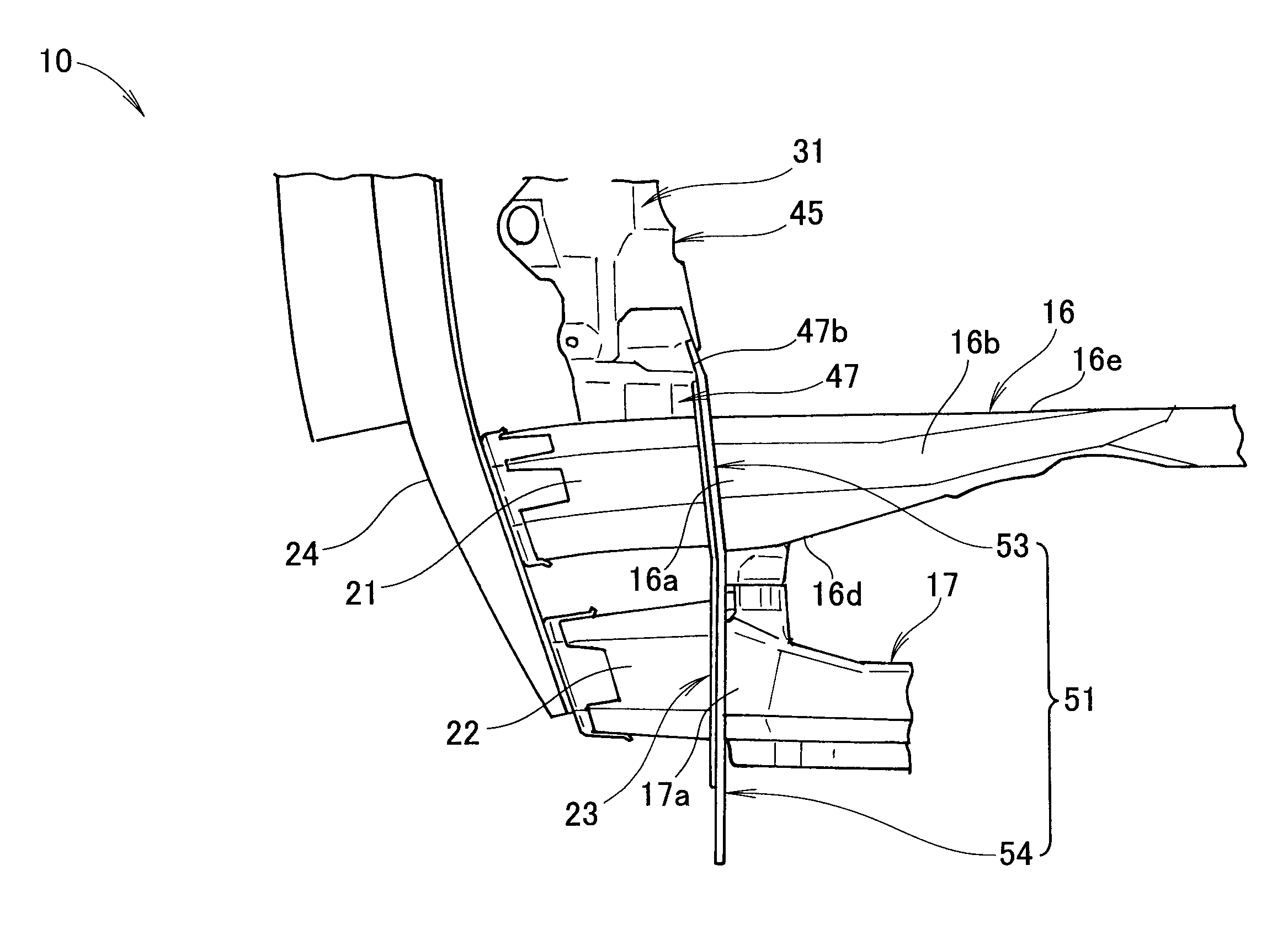
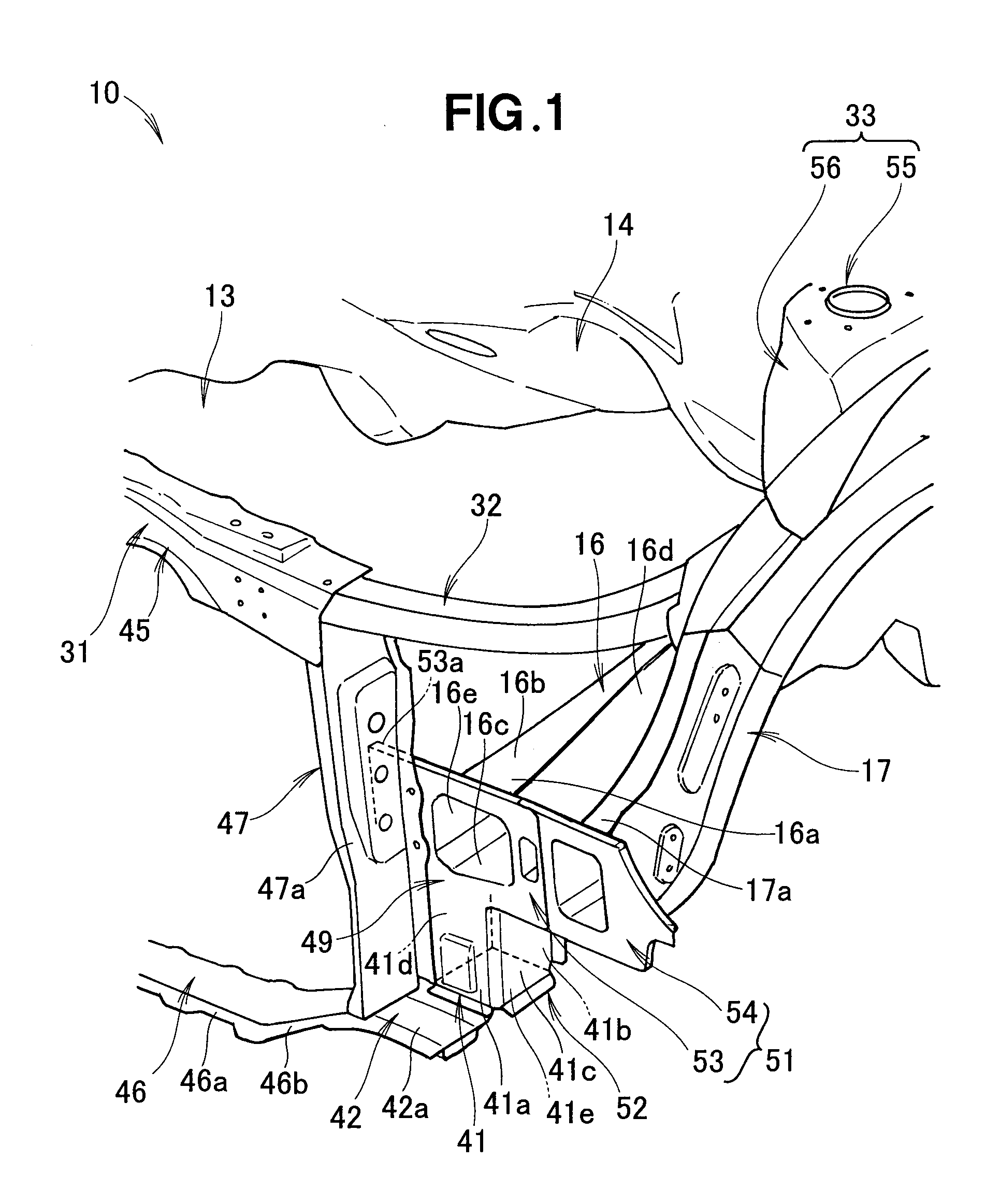
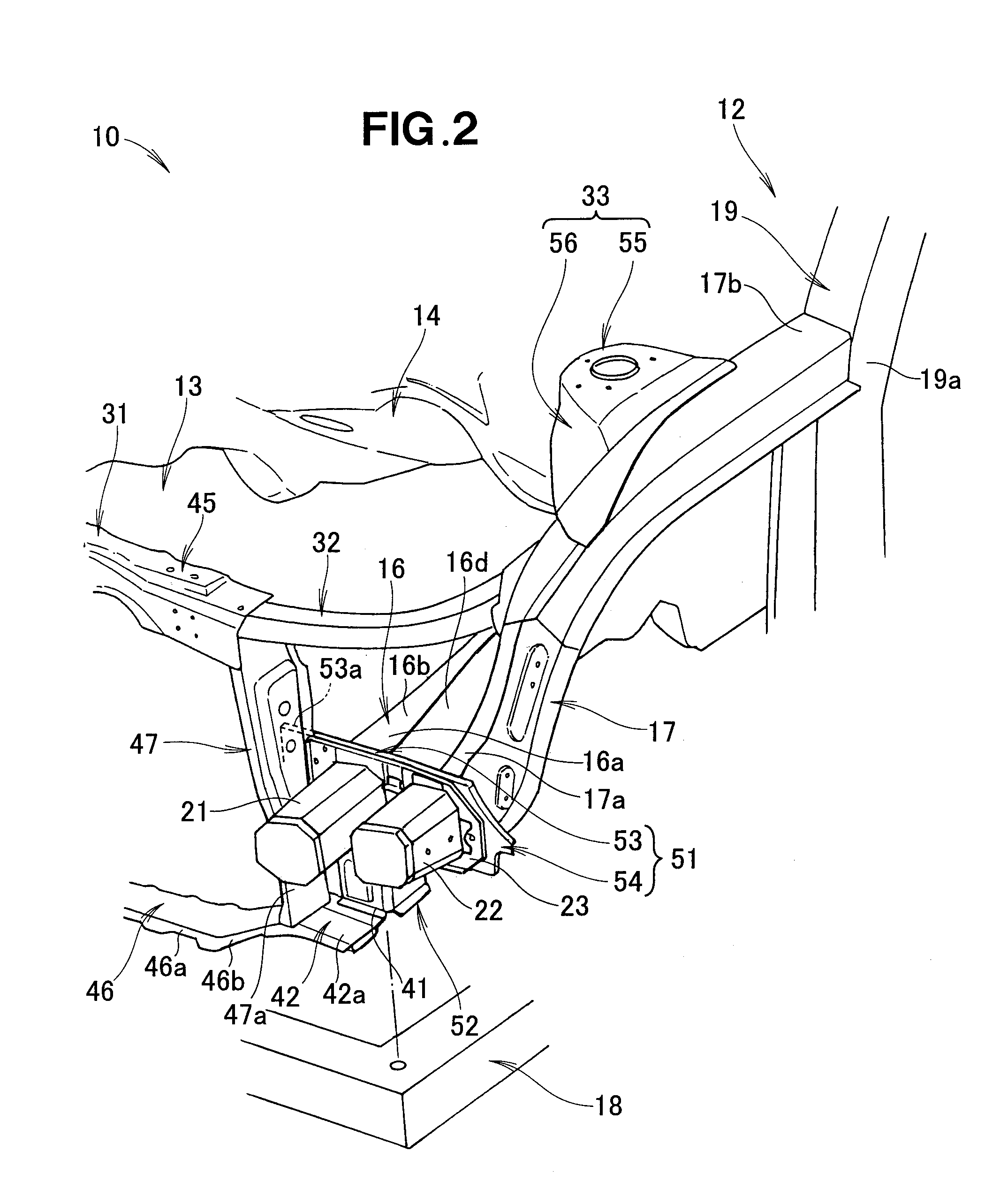
[0033]A vehicle front body structure 10 includes a front bulk head 31 formed into a rectangular shape as viewed from the front, as shown in FIGS. 1 through 5. A front side frame 16 extends longitudinally in the vehicle body at the laterally outer side of the front bulk head 31. A front sub frame 18 is supported on the bottom part of the front side frame 16, and an engine (not shown) and a gear box (not shown) are installed thereon.

[0034]An upper frame (upper member) 17 is aligned with the front side frame 16 on the outer side, and is curved upward toward the rear of the vehicle body. A rear end section 17b of the upper frame 17 is connected to a front pillar 19 forming the framework of the side front section of a passenger compartment (cabin) 12. A dashboard 14 partitions an engine compartment 13 and the cabin 12. A damper section 33 supports a damper unit (not shown). The bottom part of the damper section 33 is connected to the front side frame 16.

[0035]An impact-absorbing member (...

embodiment 2

[0067]FIG. 6 shows the vehicle front body structure according to Embodiment 2. The same symbols are used to indicate the same components as the vehicle front body structure 10 according to Embodiment 1 shown in FIG. 3, and detailed descriptions of these components are omitted. For the vehicle front body structure according to Embodiment 2, an example is presented in which one impact-absorbing member 61, wide in the lateral direction, is used instead of the two extensions of the inner inner-side impact-absorbing member 21 and the outer outer-side impact-absorbing member 22 of the vehicle front body structure of Embodiment 1.

[0068]In the vehicle front body structure 60 according to Embodiment 2, the impact-absorbing member 61 extending farther forward than the front bulk head 31 is provided to the front end part 16a of the front side frame16, and the impact-absorbing member can therefore be extended forward past the front bulk head 31. As a result, input of light collision loads to th...


PUM


Abstract

A structure of the front section of a vehicle body is disposed on the front end portion of a front side frame on the same position as the rear surface of a side stay in the front-rear direction of the vehicle body, and includes a first extending portion extending downward along the rear surface of the side stay. A lower stay is provided with a second extending portion extending outward in the vehicle width direction beyond the side stay to a position below the first extending portion. A joining section is formed so as to join the front surface of the first extending portion, the upper surface of the second extending portion, and outside surface of the side stay. The joining section defines an arrangement region for inner and outer shock absorbing members having a lower rigidity than the front side frame.

Description

TECHNICAL FIELD[0001]The present invention relates to a vehicle front body structure which includes: left and right front side frames extending longitudinally of a vehicle body in laterally outer areas of a front bulk head of rectangular shape as viewed from a front side; and an impact-absorbing member provided to the front end of the front side frames.BACKGROUND ART[0002]The thus-arranged vehicle front body structure is known as is disclosed in Patent Document 1, for example.[0003]The vehicle front body structure disclosed in Patent Document 1 comprises left and right front side frames extending longitudinally in the vehicle body at the left and right sides of the vehicle body, a bumper beam extending laterally in front of the front side frames, an impact-absorbing member (a crash pipe) connected to the left and right ends of the bumper beam and extending rearward in the vehicle body, the rear end being fastened to the front ends of the front side frames, and a front bulk head (a s...

Claims


Application Information

Patent Timeline
IPC IPC(8): B62D25/08
CPCB60R19/34B62D21/152B62D25/082B62D25/08B62D25/085
Inventor KIHARA, MAKOTOICHIKAWA, SHUJITAKEDA, TOMOYA
Owner HONDA MOTOR CO LTD
Why Eureka
Try Eureka