Rapid workpiece clamping mechanism for lathe

A clamping mechanism and workpiece technology, applied in metal processing machinery parts, clamping, manufacturing tools, etc., can solve the problems of large centrifugal force, large operating force, and many parts and so on.

Active Publication Date: 2013-09-11
LINYI JINXING MACHINE TOOL
View PDF6 Cites 5 Cited by
  • Summary
  • Abstract
  • Description
  • Claims
  • Application Information

AI Technical Summary

Problems solved by technology

This set of mechanism rotates together with the main shaft except for the joystick. There are many parts and the rear overhang of the main shaft is elongated. It has the defects of large centrifugal force and great damage to the main shaft bearing. When the speed is high, it is easy to vibrate, there is abnormal sound, and there is operating force at the same time. Large, unstable locking force, etc.

Method used


Image

  • Rapid workpiece clamping mechanism for lathe
  • Rapid workpiece clamping mechanism for lathe
  • Rapid workpiece clamping mechanism for lathe

Examples


Embodiment Construction

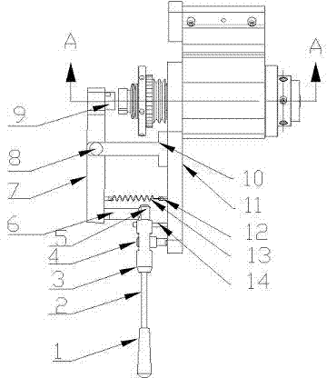
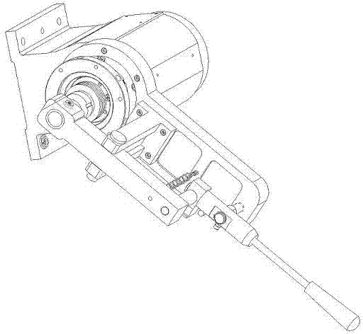
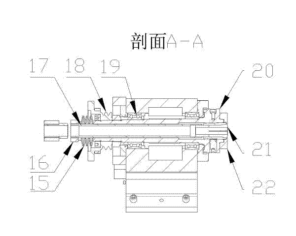
[0015] Such as figure 1 , 2 , 3, the present invention is composed of the following mechanisms: operating mechanism (handle cover 1, handle bar 2, rotating shaft 3), positioning mechanism (positioning shaft 4, support frame 10, support plate 11, pull shaft 12, extension spring 13. Locating pin 14), sliding mechanism (slope block 5), linkage mechanism (guide shaft 6, connecting rod 7, positioning shaft 2 8, top block 9), tensioning mechanism (butterfly spring 15, adjusting nut 16, Pull rod 17), clamping mechanism (collet collet 21, gland 22), rotating mechanism (belt pulley 18, main shaft bearing 19, main shaft 20).

[0016] When the handle bar 2 is in the horizontal position, there is a gap of 2-3mm between the top block 9 and the adjusting nut 16. Due to the elastic deformation force of the belleville spring, the pull bar tightens the collet, and the workpiece is in a clamped state.

[0017] When the handle bar 2 is swung downward, the rotating shaft 3 will rotate on the po...


PUM


Abstract

The invention discloses a rapid workpiece clamping mechanism for a lathe. The rapid workpiece clamping mechanism for the lathe comprises a manipulation mechanism, a positioning mechanism, a sliding mechanism, a connecting rod mechanism, a tensioning mechanism, a clamping mechanism and a rotary mechanism. Vertical swing actions of the manipulation mechanism are conversed into horizontal swing actions through matching movement of the sliding mechanism and the connecting rod mechanism to drive a pull rod to move forward to achieve the purpose of loosening a workpiece. When the connecting rod mechanism deviates from the pull rod, pulling force generated from elastic deformation of a belleville spring is capable of driving a spring clamping head to clamp the workpiece and the size of the pulling force can be adjusted through screw nut adjustment.

Description

technical field [0001] The invention relates to a structure of a machine tool component, in particular to a fast clamping mechanism for a workpiece used in a lathe. Background technique [0002] The workpiece quick clamping mechanism currently used in lathes is to push the passive disc installed on the main shaft through the movement of the joystick parallel to the main shaft direction, and open the three cam claws through the arc surface on the passive disc. , so as to drive the pull rod to move back and forth to realize the clamping and loosening of the workpiece. The clamping force and stroke are realized by adjusting the distance of the support plate installed behind the cam claw. This set of mechanism rotates together with the main shaft except for the joystick. There are many parts and the rear overhang of the main shaft is elongated. It has the defects of large centrifugal force and great damage to the main shaft bearing. When the speed is high, it is easy to vibrate...

Claims


Application Information

Patent Timeline
IPC IPC(8): B23Q3/12
Inventor 王文剑程传伟郭崇才
Owner LINYI JINXING MACHINE TOOL
Why Eureka
Try Eureka