Inductor for surface mounting

a surface mounting and inductance technology, applied in the direction of transformer/inductance details, transformer/react mounting/support/suspension, electrical equipment, etc., can solve the problems of large volume, large volume, and large volume of winding wire that includes a circular cross section, so as to reduce size or dimension or structure, easily and quickly and readily attached or mounted or secured

Inactive Publication Date: 2013-08-15
MAG LAYERS SCI TECHNICS
View PDF2 Cites 6 Cited by
  • Summary
  • Abstract
  • Description
  • Claims
  • Application Information

AI Technical Summary

Benefits of technology

[0012]The primary objective of the present invention is to provide an inductor including a reduced size or dimension or structure for allowing the inductor to be suitably and easily and quickly and readily attached or mounted or secured onto the surfaces of the electric circuit boards or the like.

Problems solved by technology

However, the ends of the coil may not be easily and quickly and readily attached or mounted or secured onto the surfaces of the electric circuit boards or the like with working machines, and should be mounted manually such that the specialized or trained workers may take a long time to mount the typical inductors manually.
However, the winding wire that includes a circular cross section may also occupy a large volume, and the terminals of the winding wire also includes a circular cross section and may not be easily and quickly and readily attached or mounted or secured onto the surfaces of the electric circuit boards or the like with working machines, and should be mounted manually such that the specialized or trained workers may take a long time to mount the typical inductors manually.

Method used


Image

  • Inductor for surface mounting
  • Inductor for surface mounting
  • Inductor for surface mounting

Examples


Embodiment Construction

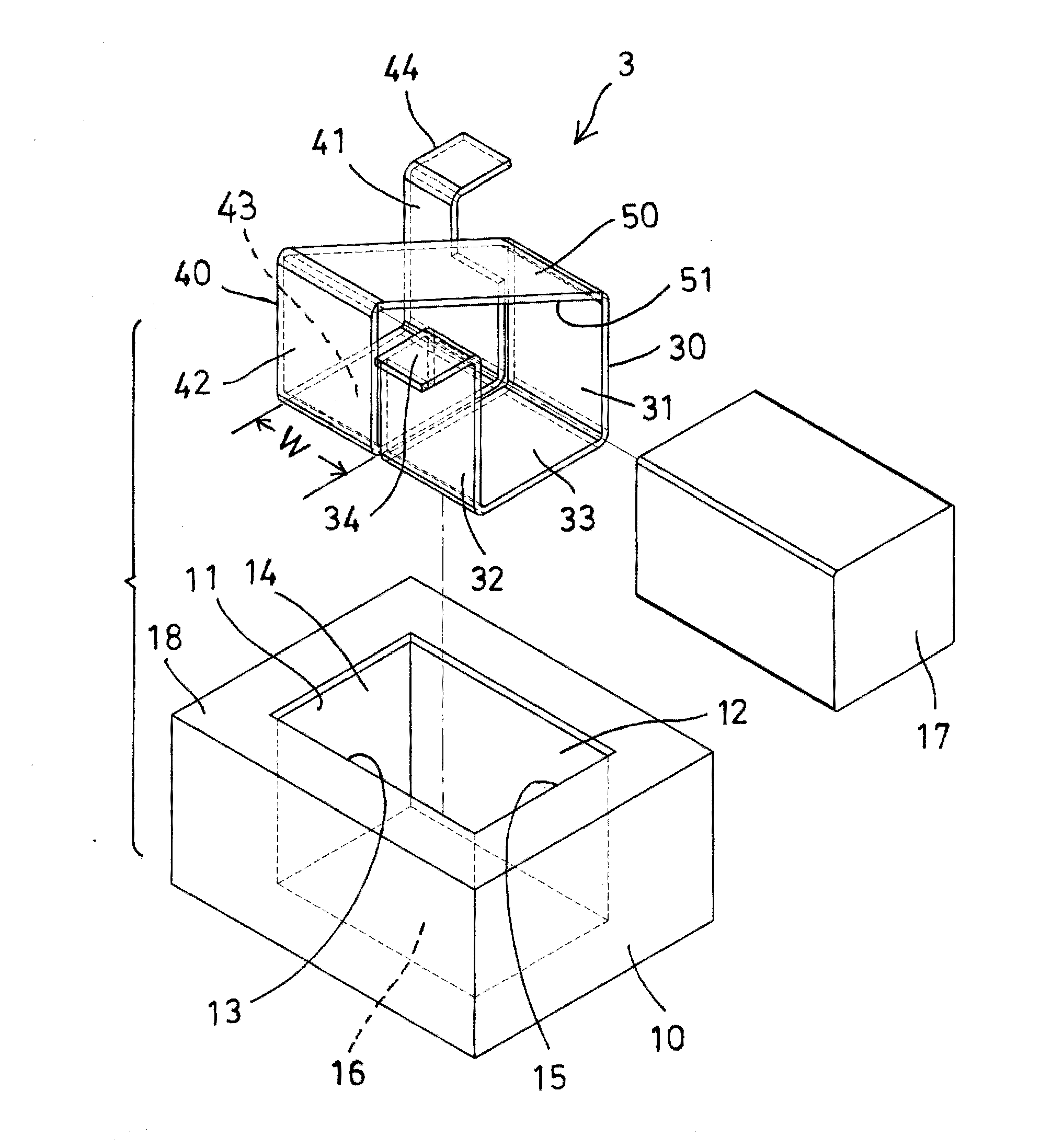
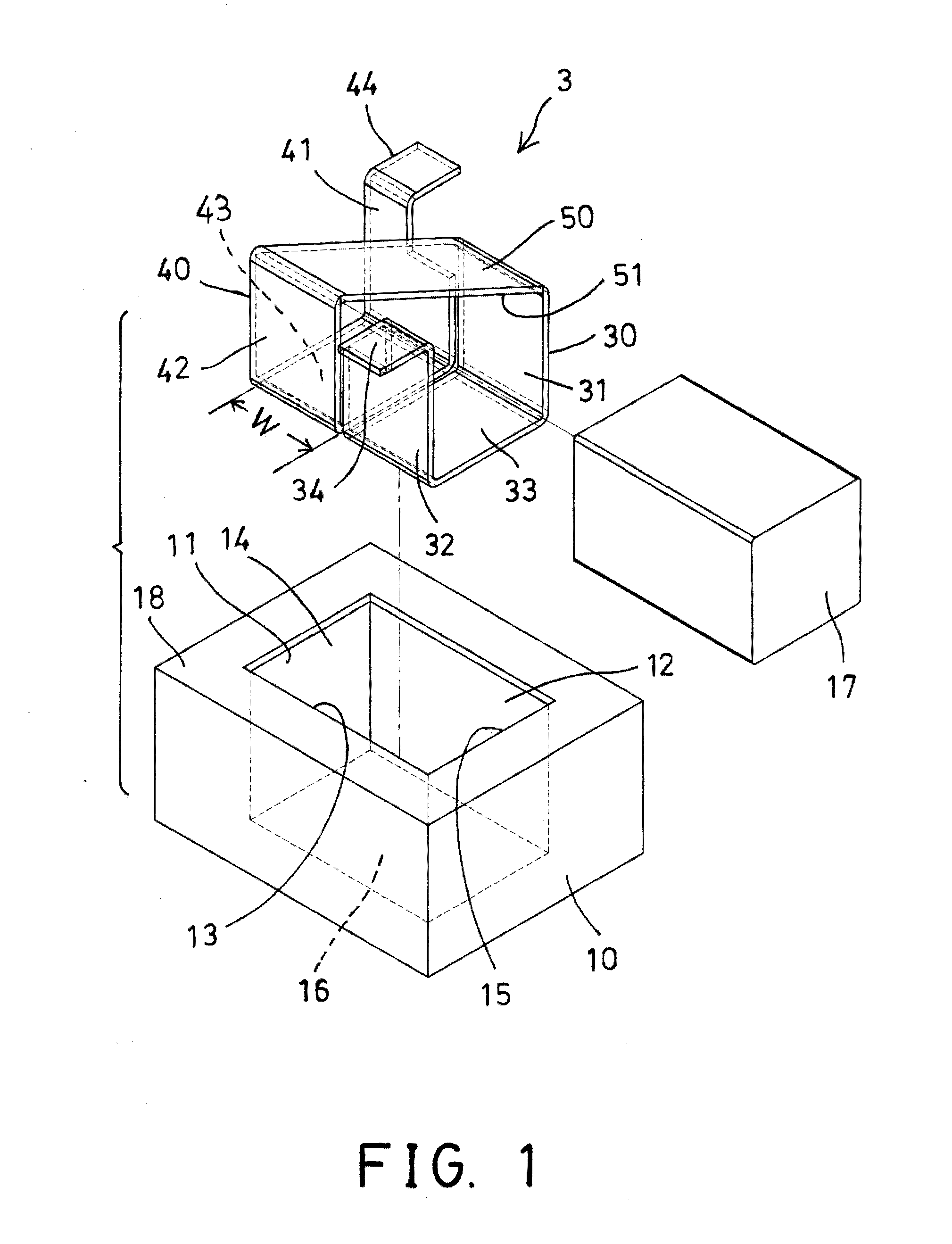
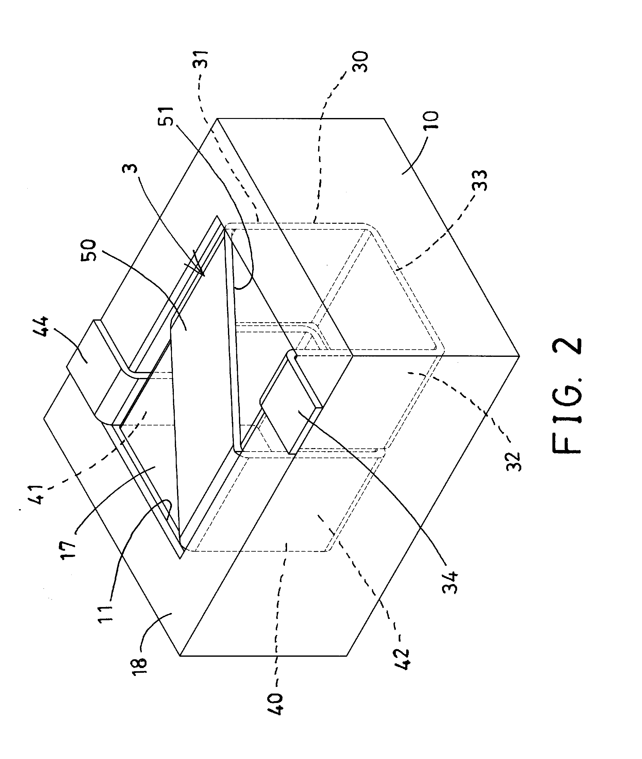
[0025]Referring to the drawings, and initially to FIGS. 1-3, an inductor in accordance with the present invention comprises a first or lower or outer core or base device 10 including a chamber 11 formed therein and having a parallelepiped shape or structure and formed or defined by two opposite side surfaces 12, 13, and two opposite end surfaces 14, 15, and / or a bottom wall 16 (FIG. 3), such that the chamber 11 of the base device 10 is opened upwardly, but may also be opened downwardly having no bottom surface formed therein. A second or inner core 17 may further be provided and received or engaged in the chamber 11 of the base device 10.

[0026]A coil member or conductive device 3 is further provided and includes one or more (such as two) coil sections or segments or elements 30, 40 each having a U-shaped structure and each having two opposite side panels 31, 32; 41, 42 and a bottom panel 33, 43 connected or coupled between the bottom portions of the side panels 31, 32; 41, 42 respec...


PUM

PropertyMeasurementUnit
shapeaaaaaaaaaa
conductiveaaaaaaaaaa
thicknessaaaaaaaaaa

Abstract

An inductor includes a base device having a parallelepiped chamber formed by two side surfaces and two end surfaces, a parallelepiped conductive device engaged into the parallelepiped chamber of the base device and having a parallelepiped compartment and having two terminals engaged onto an upper surface of the base device, and a core engaged into the parallelepiped compartment of the conductive device. The conductive device is planar and includes a rectangular cross section having a reduced dimension or structure for allowing the inductor to be easily and quickly and attached onto the surfaces of the electric circuit boards with surface mount devices.

Description

BACKGROUND OF THE INVENTION[0001]1. Field of the Invention[0002]The present invention relates to an inductor, and more particularly to an inductor including a reduced size or dimension or structure for allowing the inductor to be suitably and easily and quickly and readily attached or mounted or secured onto the surfaces of the electric circuit boards or the like.[0003]2. Description of the Prior Art[0004]Typical inductors have been developed and provided for inducing the current and comprise one or more cores and one or more coils or conductive members for inducing or generating the current.[0005]For example, U.S. Pat. No. 5,751,203 to Tsutsumi et al. discloses one of the typical inductors also comprising one or more coils or conductive members engaged into a drum-shaped core for inducing or generating the current, and a cylindrical core disposed around the drum-shaped core and the coil, and a terminal table attached or mounted or engaged onto the drum-shaped core and the coil and ...

Claims


Application Information

Patent Timeline
Patent Type & Authority Applications(United States)
IPC IPC(8): H01F27/29
CPCH01F27/292H01F27/2847H01F27/263
Inventor YEH, HSIU FACHEN, PIN YULU, HANG CHUNWEN, CHEN KUO
Owner MAG LAYERS SCI TECHNICS
Why Eureka
Try Eureka