Eureka AIR delivers breakthrough ideas for toughest innovation challenges, trusted by R&D personnel around the world.

Magnesium metal-air battery

Active Publication Date: 2013-08-15
SUWEI ASSOC
View PDF1 Cites 11 Cited by
  • Summary
  • Abstract
  • Description
  • Claims
  • Application Information

AI Technical Summary

Benefits of technology

The patent describes two types of magnesium metal-air batteries. The first type has a positive electrode-side catalyst layer that is stacked on the positive current collector, which results in a sufficient discharge capacity. The second type, which has a U-shaped separator and positive current collector surrounding the negative electrode in this order, produces higher output current than the first type. Overall, the patent describes how to improve the performance of magnesium metal-air batteries by optimizing the catalyst layer and separator design.

Problems solved by technology

However, the magnesium manganese dioxide batteries disclosed in the above patent documents 1 and 2 have the technical defects or drawbacks in that, since the formation of passive state film on the surface of the negative electrode cannot be efficiently restricted, it is impossible or difficult to achieve sufficient discharge capacity.
Further, the magnesium battery disclosed in the patent document 3 has a drawback in that, although the capacity of the negative electrode formed of magnesium can be used well in cell performance, the positive electrode cannot efficiently or fully utilize the capacity of the negative electrode made of magnesium.
Still further, the air magnesium battery disclosed in the non-patent document 1 has a technical problem in that sufficient discharge capacity cannot be achieved as shown in FIG. 5 of the document.

Method used


Image

  • Magnesium metal-air battery
  • Magnesium metal-air battery
  • Magnesium metal-air battery

Examples


embodiment 1

[0058]Now, some preferred embodiments of the present invention will be explained in detail with reference to the accompanying drawings. It should be noted that, throughout the drawings, the same or like reference numerals denote the same or like parts.

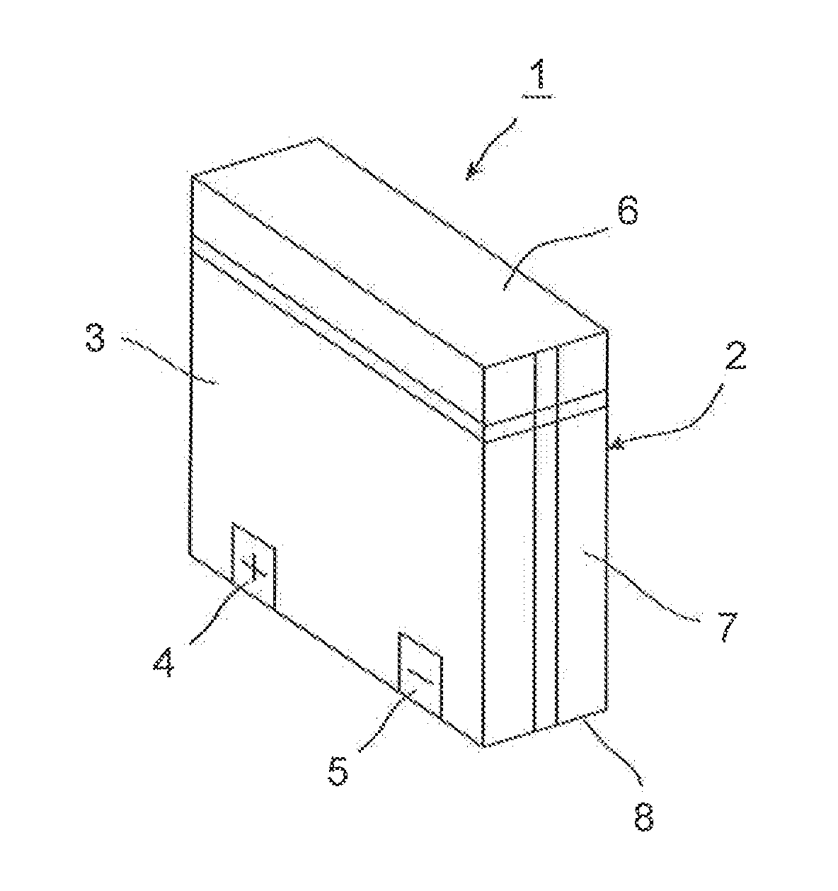
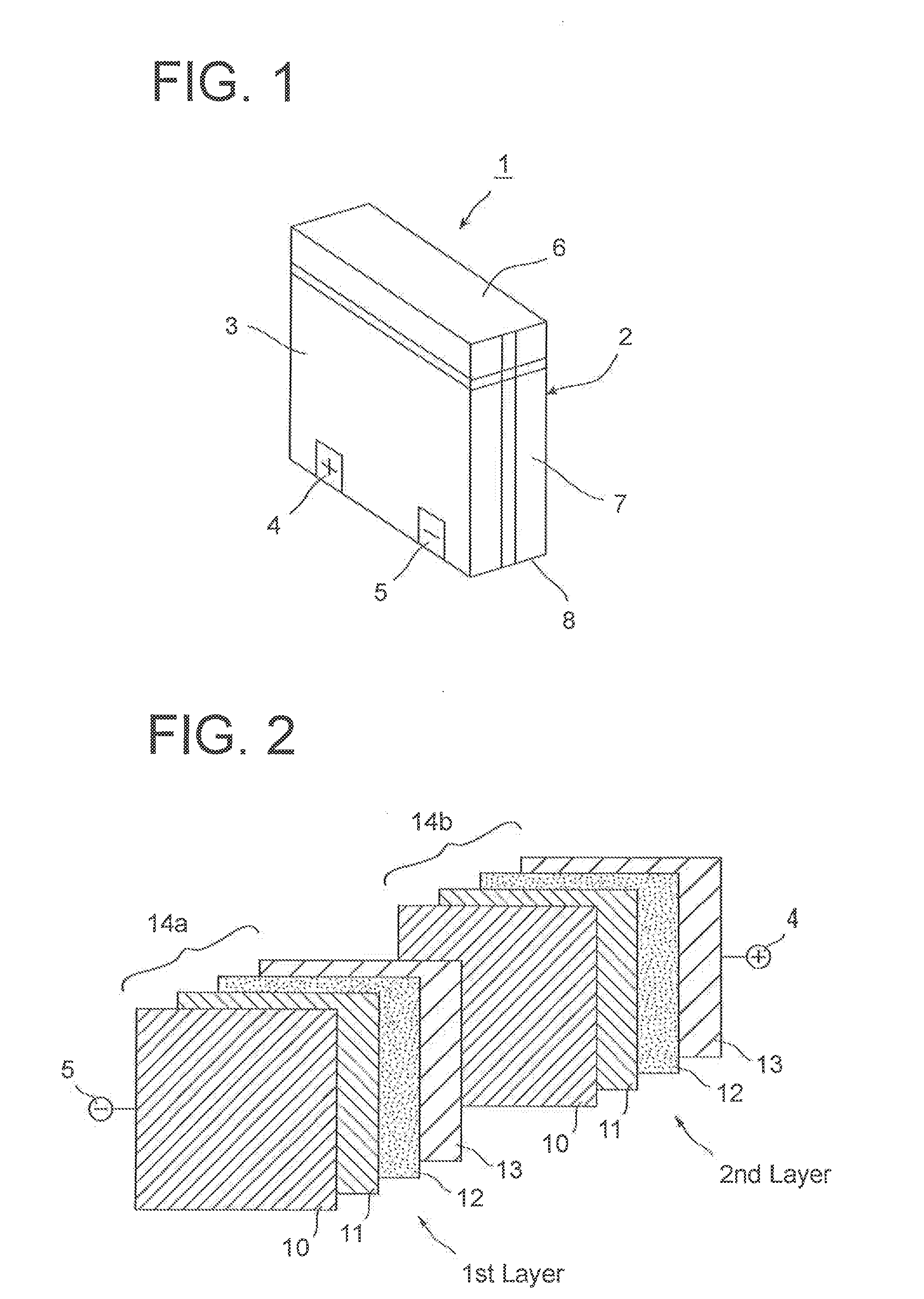
[0059]FIG. 1 a diagrammatic perspective view which shows a magnesium metal-air battery of the first embodiment of the present invention. As shown in FIG. 1, the magnesium metal-air battery 1 has a battery enclosure 2 of a rectangular parallelepiped shape. The thickness of the enclosure 2 is comparatively thin. It should be noted that the shape of the enclosure 2 is not limitative to the illustrated rectangular shape but may be any given shape depending on the necessity. The battery enclosure 2 has for example, at a lower portion of its one side-wall 3, a positive terminal 4 and a negative terminal 5. The position where the positive and negative terminals 4 and 5 are arranged is not limited to the illustrated lower portion of the side-w...

embodiment 2

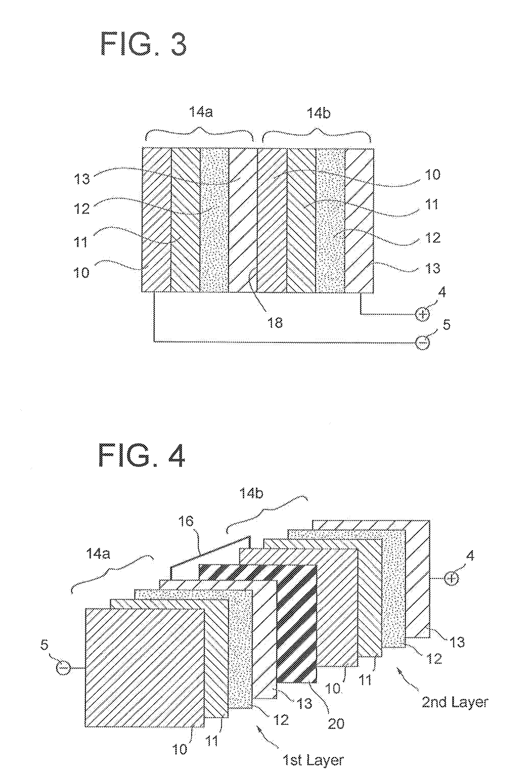
[0108]Now, magnesium metal-air battery of the second embodiment 2 according to the invention will be explained with reference the accompanying drawings. The parts or elements constituting the battery of this embodiment 2, corresponding to the same or like parts or elements of the battery of the above explained first embodiment are denoted with same reference numerals of the first embodiment. Here, no further explanation is made for such same parts or elements. The feature of this embodiment is that, as clearly illustrated in FIG. 5 of a diagrammatic exploded view and FIG. 6 of a sectional view, two sets of separators 11, positive electrode-side catalyst layers 12 and current collectors 13 are symmetrically arranged at both sides with the common negative electrode 10 being positioned as a center. The positive current collector 13 which is arranged at the outermost position is folded into a U-shape and two inner walls oppose to both the sides of the negative electrode 10. Inner spaces...


PUM


Abstract

Disclosed is a magnesium metal-air battery in which capacity of a negative electrode made of magnesium or its alloy is sufficiently utilized for battery performance and which has a positive electrode material which is capable of coping with the capacity of the negative electrode. The magnesium metal-air battery includes at least one unit battery cell. The cell comprises a negative electrode made of magnesium or its alloy; a positive electrode-side catalyst layer including, as positive active material, activated carbon for absorbing oxygen in air, anhydrous poly-carboxylate, manganese and metal powder; a positive current collector which is made of conductive material and which is laminated on the positive electrode-side catalyst layer; and a separator which allows passing of ions between the negative electrode and the positive electrode-side catalyst layer while it separates therebetween. The positive electrode-side catalyst layer may further include carbon black, metal chloride and graphite. In use, where water or metal chloride solution is supplied to at least the positive electrode-side catalyst layer, an electromotive force is generated between the negative electrode and the positive current collector. In the case where a plurality of unit battery cells are connected in series, an insulator is provided therebetween.

Description

TECHNICAL FIELD[0001]The present invention relates to a magnesium metal-air battery which utilizes oxygen in the air and manganese dioxide as positive active material.BACKGROUND OF TECHNICAL FIELD[0002]Development of next generation cell or battery relating to the next generation vehicle and the introduction and spread of renewable energy is one of the recent attractive technologies which contribute to enhancement in the industrial competitiveness of Japan. In the fields of the next generation batteries, in addition to the efforts of further improvement of performance of lithium batteries which are presently used widely, research and development of new rechargeable cell or battery (secondary battery) or power generation cell or battery (primary battery) which takes the place of lithium batteries are now being conducted actively.[0003]As the next generation battery which takes the place of lithium batteries, there are cells or batteries which use magnesium. Magnesium presents in the ...

Claims


Application Information

Patent Timeline
IPC IPC(8): H01M4/90
CPCH01M12/06Y02E60/50H01M4/9083H01M4/9008H01M4/9016H01M4/9041
Inventor SUZUKI, SUSUMU
Owner SUWEI ASSOC
Why Eureka
Eureka Blog
Learn More