Femoral prosthesis with an offset head

a technology of femoral prosthesis and offset head, which is applied in the field of femoral prosthesis, can solve the problems of affecting the quality of femoral prosthesis, and affecting the quality of femoral prosthesis, and achieves the effect of simple machine during manufactur

Inactive Publication Date: 2013-08-15
STRYKER IRELAND LTD
View PDF6 Cites 36 Cited by
  • Summary
  • Abstract
  • Description
  • Claims
  • Application Information

AI Technical Summary

Benefits of technology

[0018]This protrusion and indent feature ensures that the head part can be fitted at a particular pre-determined rotational position on the spigot, so the intended positional adjustment is achieved, and also that that any offset rotational loading experienced post procedure will not lead to failure of the surface contact between the spigot and the bore because these surfaces will not experience any rotational shear stress. Depending on the shape and configuration of the protrusion and the indent, this feature also allows for a particular number of specific rotational fitting positions for the head part. For example, a head part can be fitted in one of four rotational positions, each of which provides a known positional adjustment in a particular direction. As such, a head part with the correct oblique angle between the bore and polar axes can be chosen from a set, and then fitted in a particular one of its possible rotational positions to arrive at the correct formation. There is no need to estimate a correct rotational fitting position during the procedure.
[0019]The protrusion can be formed on the spigot and the indent in the bore, but in a preferred embodiment the bore can comprise a base surface at an inner end thereof, the spigot can comprise a free end face, and the protrusion can be formed on the base surface and the indent on the free end face. The formation of the protrusion and indent on these two surfaces is relatively simple to machine during manufacture.

Problems solved by technology

Misalignment can lead to problems such as excessive wear or local tissue damage post procedure, and revision surgery may then be required.
The degree of the offset angle also determines the resulting leg length and the soft tissue tension across the joint, and again if this is not right then it can lead to problems post-procedure.
However, all patents are different and traditional stem and head configurations of this kind only provide a limited number of possibilities.
However, these three-part femoral prostheses comprise two taper junctions, which significantly weakens the prosthesis and doubles the potential points of failure.
There can also be metal corrosion at the taper junctions leading to Co and Cr ions being released which can cause an inflammatory reaction in the patient.
Further, there are only a certain number of possibilities which can practically be provided in a set, and micro adjustment between the fixed parts is not possible.
However, there are three problems with the device shown in Brooks.
Firstly, it does not provide any angular adjustment between the head part and the stem part.
Secondly, by displacing the axis of the bore from the polar axis of the bearing surface, any rotational loading of the head part post procedure acts to destabilize the taper joint between these parts, which is a serious extra potential cause of failure.
Thirdly, the scope of adjustment provided by one free rotational facility is fairly limited, and as such in the embodiment shown in Brooks a second free rotational facility is provided by means of an intermediate spigot component for fitment between the stem part and the head part.

Method used


Image

  • Femoral prosthesis with an offset head
  • Femoral prosthesis with an offset head
  • Femoral prosthesis with an offset head

Examples


Embodiment Construction

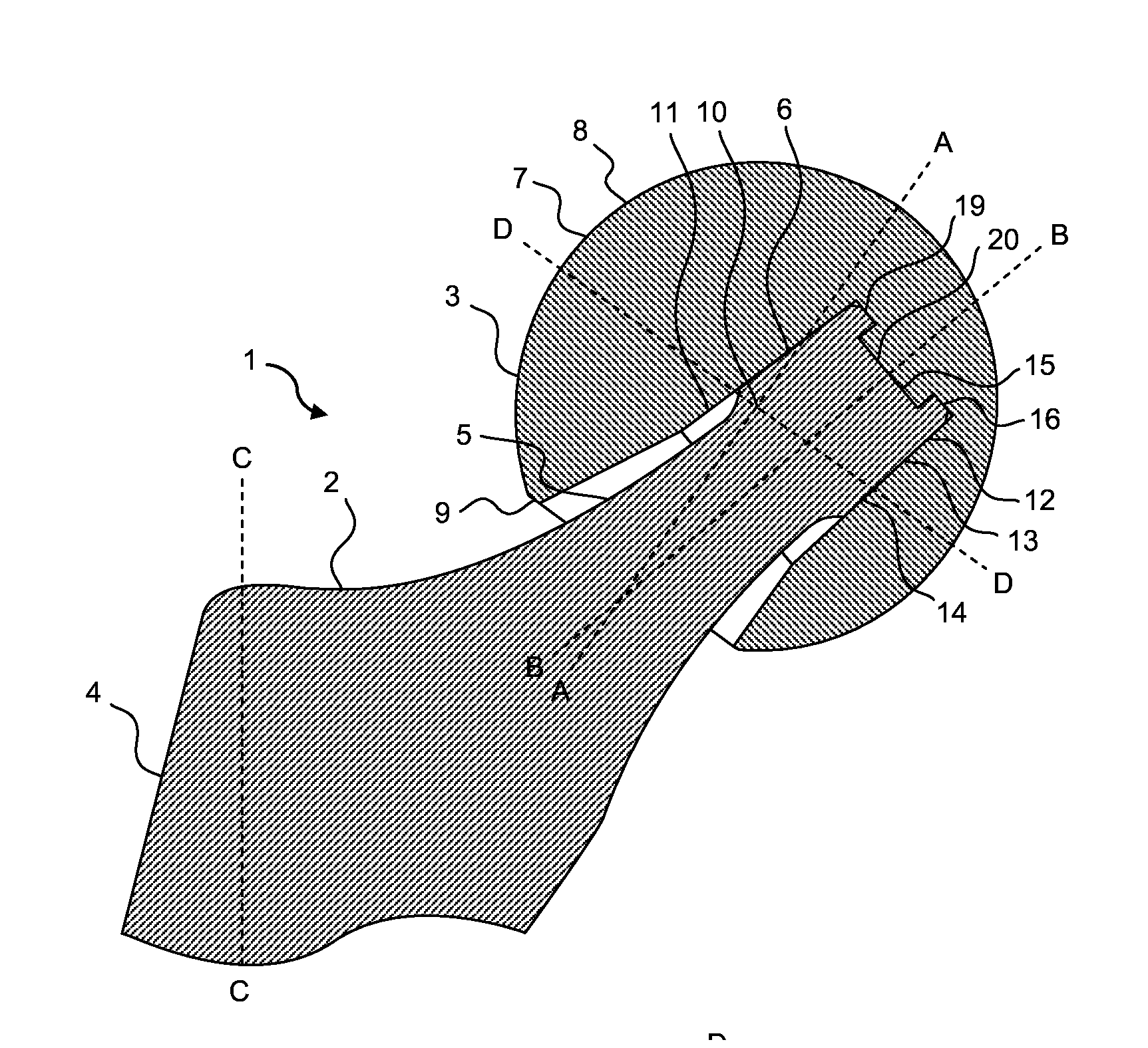
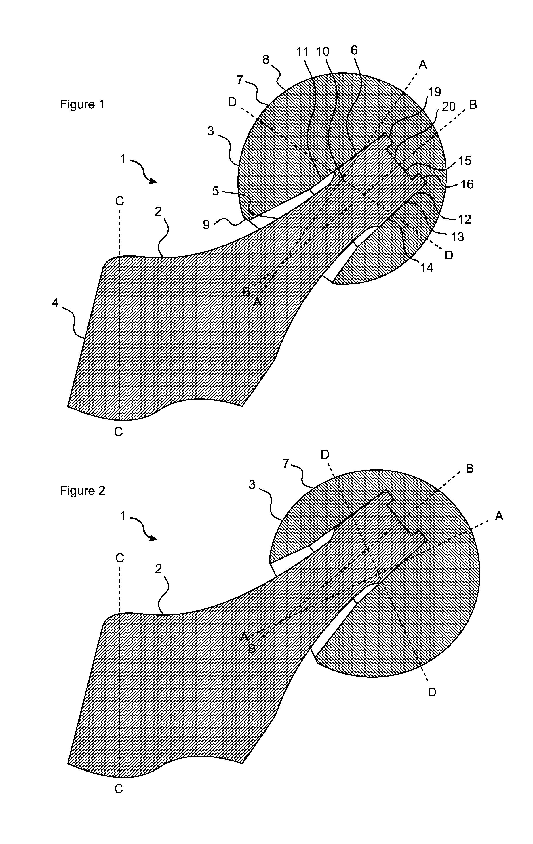
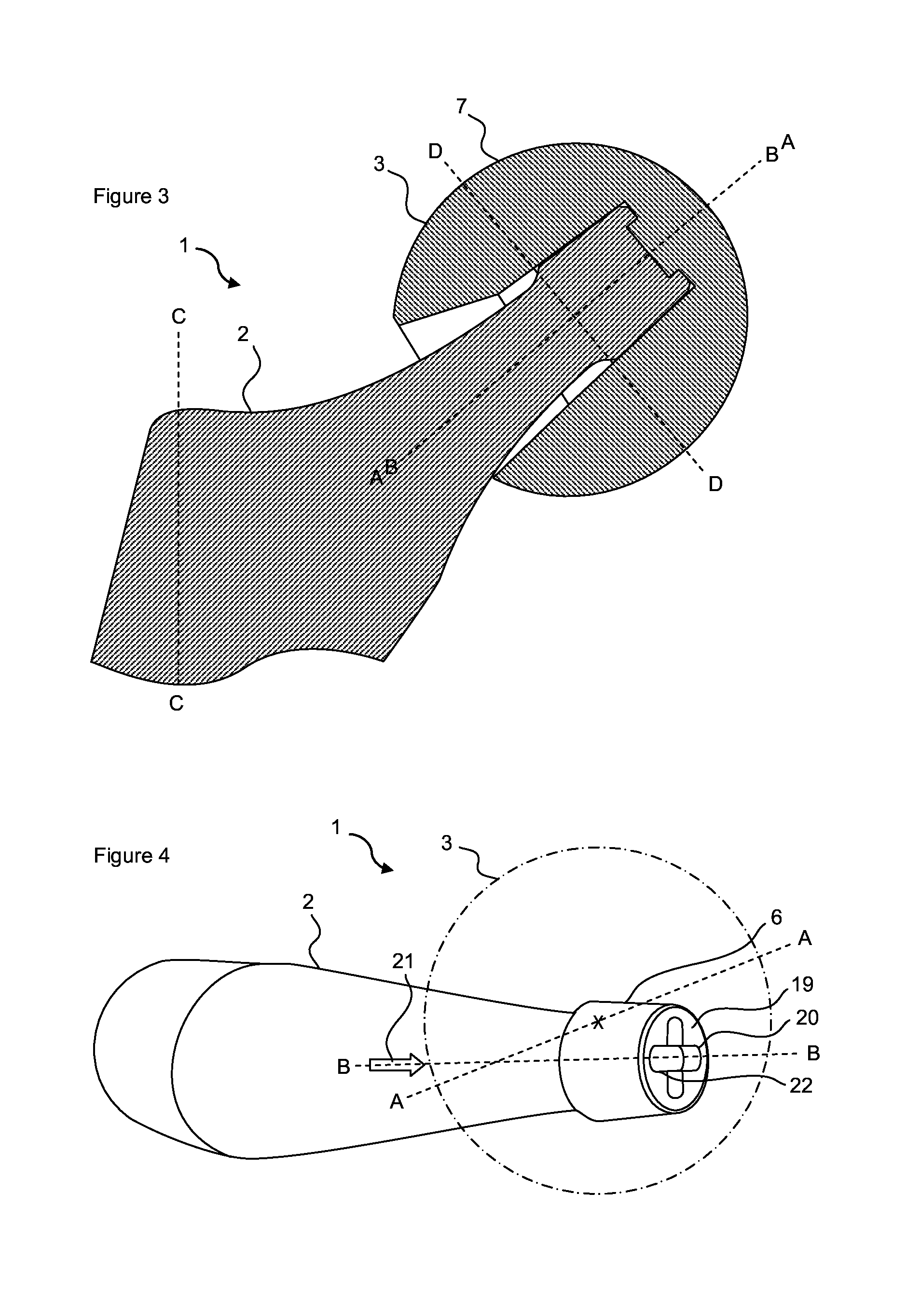
[0039]As shown in FIG. 1a femoral prosthesis 1 comprises a stem part 2 and a head part 3, in which the stem part 2 comprises a body section 4 for location in the femur of a patient (not shown) and a neck section 5 comprising a spigot 6, in which the head part 3 comprises a bearing surface 7 formed as part of a sphere 8 and a reverse side 9, in which the bearing surface 7 comprises a polar axis A-A extending through a center 10 of the sphere 8 formed thereby, in which a bore 11 is provided in reverse side 9 adapted to receive spigot 6, in which bore 11 comprise a bore axis B-B, and in which bore axis B-B is oblique to polar axis A-A.

[0040]The stem part 2 is similar to known stem parts of femoral prostheses, and comprises a tapering body section 4 (which is only partially shown in the FIGS.) for location in the intramedullary cavity of the patient's femur (not shown) in the known way. The body section 4 comprises a body axis C-C, and the neck section 5 carries spigot 6 at angle to the...


PUM


Abstract

A femoral prosthesis has a stem part and a head part, in which the stem part has a body section for location in the femur of a patient and a neck section including a trunion or spigot. The head part has a bearing surface formed as part of a sphere and a reverse side. The bearing surface has a polar axis extending through a center of the sphere formed thereby. A bore is provided in the reverse side adapted to receive the spigot wherein the bore comprise a bore axis, and in which the bore axis is oblique to the polar axis.

Description

CROSS-REFERENCE TO RELATED APPLICATION[0001]The present application claims priority from Great Britain Patent Application No. 1202367.7 filed Feb. 10, 2012, the disclosure of which is hereby incorporated herein by reference.BACKGROUND OF THE INVENTION[0002]The present invention relates to a femoral prosthesis for use in hip joint replacement procedures.[0003]Femoral prostheses comprise a stem part and a head part. The stem part comprises a body section for location in the intramedullary cavity of the patient's femur, and a neck section at its upper end for carrying the head part. The head part comprises a bearing surface formed as part of a sphere, which is for articulation in a cup component implanted into the patient's acetabulum. The stem part and the head part are separate components which are connected together during the procedure. The neck section of the stem part comprises a tapered trunion or spigot, and a reverse side of the head part comprises a tapered bore adapted to re...

Claims


Application Information

Patent Timeline
Patent Type & Authority Applications(United States)
IPC IPC(8): A61F2/36
CPCA61F2002/3613A61F2002/365A61F2002/30143A61F2002/30153A61F2002/30154A61F2002/30156A61F2002/30163A61F2002/30166A61F2002/30171A61F2002/30332A61F2002/30367A61F2002/30377A61F2002/30494A61F2002/3053A61F2002/3054A61F2002/3611A61F2/3609A61F2002/30179
Inventor CUEILLE, CHRISTOPHE
Owner STRYKER IRELAND LTD
Why Eureka
Try Eureka