Time-of-flight camera for a motor vehicle, motor vehicle and method for operating a time-of-flight camera

a technology for time-of-flight cameras and motor vehicles, which is applied in the direction of instruments, computing, measurement devices, etc., and can solve problems such as unfavorable options

Inactive Publication Date: 2013-08-15
AUDI AG
View PDF12 Cites 25 Cited by
  • Summary
  • Abstract
  • Description
  • Claims
  • Application Information

AI Technical Summary

Benefits of technology

[0004]Time-Of-Flight cameras (often also referred to in short as TOF cameras) are largely known in the state of the art and are increasingly used in motor vehicles. The advantage of a Time-Of-Flight camera is that beside image information, it also provides items of three-dimensional information. This means, each pixel can be assigned an item of distance information. For measuring the distance, a TOF method is used from which the name of this measuring device is derived.

Problems solved by technology

For improving the adjustment to different driving situations the Time-Of-Flight camera, i.e., concretely the camera unit and the illumination unit may be provided with a zoom optic to thereby configure the opening angle and the range adjustable, which is not a feasible option, however, due to the complexity and the costs of such a system.

Method used


Image

  • Time-of-flight camera for a motor vehicle, motor vehicle and method for operating a time-of-flight camera
  • Time-of-flight camera for a motor vehicle, motor vehicle and method for operating a time-of-flight camera
  • Time-of-flight camera for a motor vehicle, motor vehicle and method for operating a time-of-flight camera

Examples


Embodiment Construction

[0027]Throughout all the Figures, same or corresponding elements are generally indicated by same reference numerals. These depicted embodiments are to be understood as illustrative of the invention and not as limiting in any way. It should also be understood that the drawings are not necessarily to scale and that the embodiments are sometimes illustrated by graphic symbols, phantom lines, diagrammatic representations and fragmentary views. In certain instances, details which are not necessary for an understanding of the present invention or which render other details difficult to perceive may have been omitted.

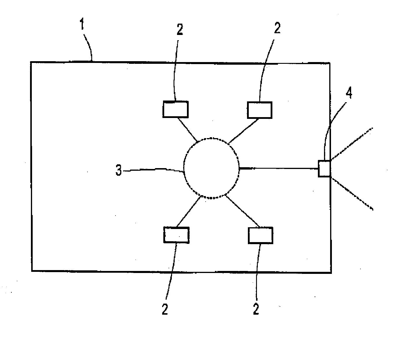
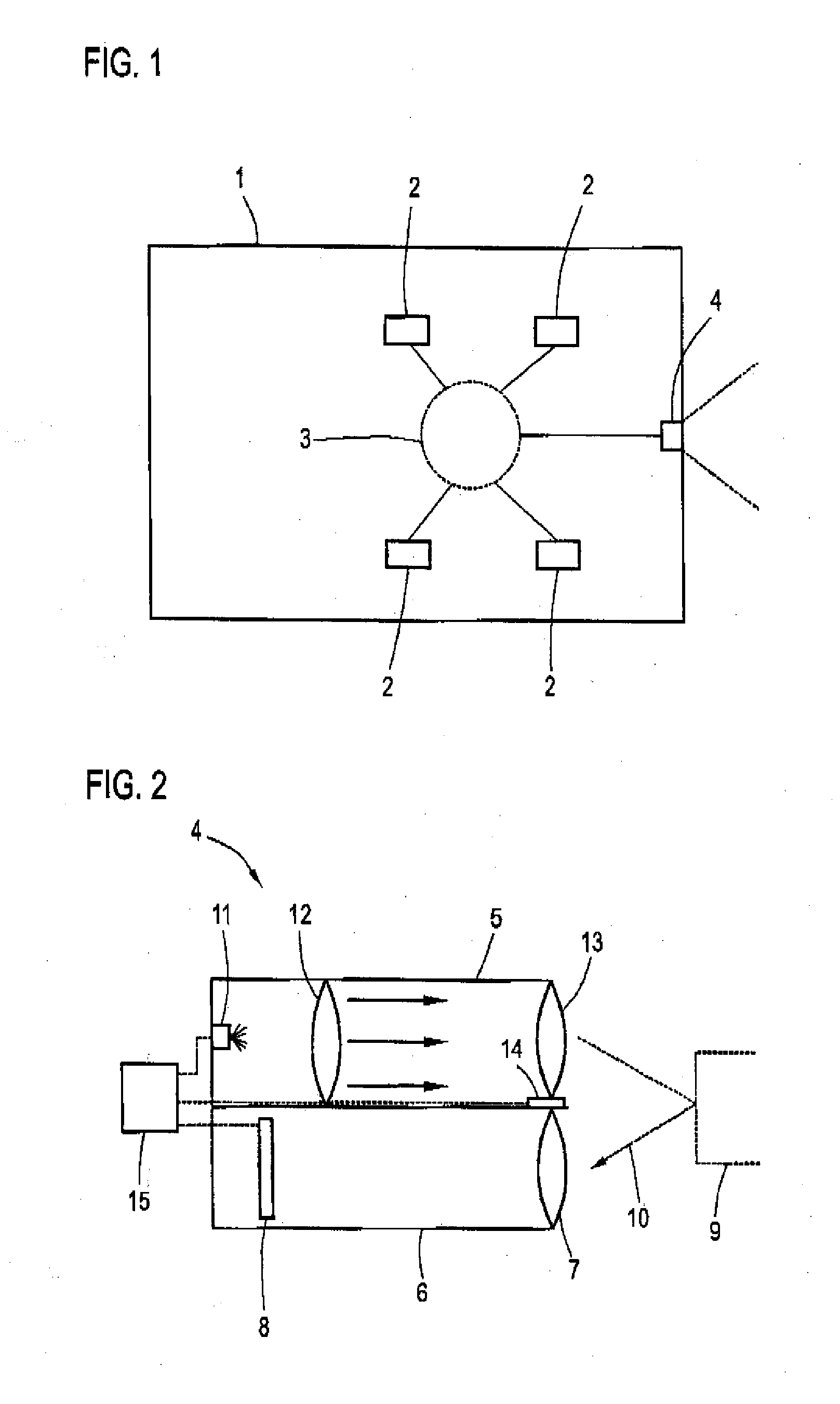
[0028]Turning now to the drawing, and in particular to FIG. 1, there is shown a schematic diagram of a motor vehicle 1 according to the invention. The latter has, as is generally known, a multitude of vehicle systems 2, several of which are outlined exemplary in FIG. 2. These vehicle systems include driver assist systems, control devices, sensors and the like. They communicate...


PUM


Abstract

A Time-Of-Flight camera for a motor vehicle includes an illumination unit with a light source and an optic for illuminating an illumination area, a camera unit for measuring measuring data and a control unit, wherein light emitted by the light source and reflectively detected by the camera unit is analyzable for determination of a distance information, wherein at least one piezoelectric actuating device is operably connected to the optic for adjusting the illumination area, and the control unit is configured for controlling the actuation device in dependence on at least one operating parameter which describes the driving situation of the motor vehicle.

Description

CROSS-REFERENCES TO RELATED APPLICATIONS[0001]This application claims the priority of German Patent Application, Serial No. 10 2012 002 922.5, filed Feb. 14, 2012, pursuant to 35 U.S.C. 119(a)-(d), the disclosure of which is incorporated herein by reference.BACKGROUND OF THE INVENTION[0002]The invention relates to a Time-Of-Flight camera for a motor vehicle, a motor vehicle with such a Time-Of-Flight camera and a method for operating such a Time-Of-Flight camera.[0003]The following discussion of related art is provided to assist the reader in understanding the advantages of the invention, and is not to be construed as an admission that this related art is prior art to this invention.[0004]Time-Of-Flight cameras (often also referred to in short as TOF cameras) are largely known in the state of the art and are increasingly used in motor vehicles. The advantage of a Time-Of-Flight camera is that beside image information, it also provides items of three-dimensional information. This mea...

Claims


Application Information

Patent Timeline
Patent Type & Authority Applications(United States)
IPC IPC(8): G06F17/00G01S17/894G01S17/931
CPCG06F17/00G01S7/4814G01S17/936G01S17/89G01S17/931G01S17/894
Inventor ROEHDER, MARTIN
Owner AUDI AG
Why Eureka
Try Eureka