Method for determining the position of a rotation axis

a technology of rotation axis and method, which is applied in the direction of speed measurement using gyroscopic effects, instruments, basic electric elements, etc., can solve the problems of insufficient connection of corresponding contacts to each other, time-consuming and accordingly costly check, etc., and achieves the effect of faster and more accura

Active Publication Date: 2013-08-15
EV GRP E THALLNER GMBH
View PDF3 Cites 0 Cited by
  • Summary
  • Abstract
  • Description
  • Claims
  • Application Information

AI Technical Summary

Benefits of technology

[0005]The object is therefore to develop a method with which the above-mentioned technical problems can be solved so that a faster, and acco

Problems solved by technology

In the case of an inaccurate orientation or movement of the semiconductor components, in particular the contact points of the semiconductor components on the opposite sides of the wafer, the corresponding contacts would not—or not adequately—be connected to one another.
Since

Method used


Image

  • Method for determining the position of a rotation axis
  • Method for determining the position of a rotation axis
  • Method for determining the position of a rotation axis

Examples


Embodiment Construction

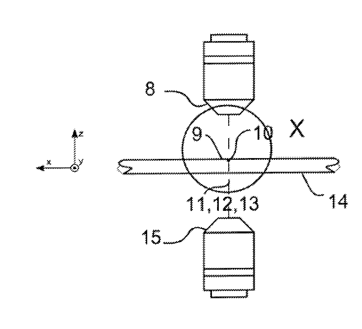
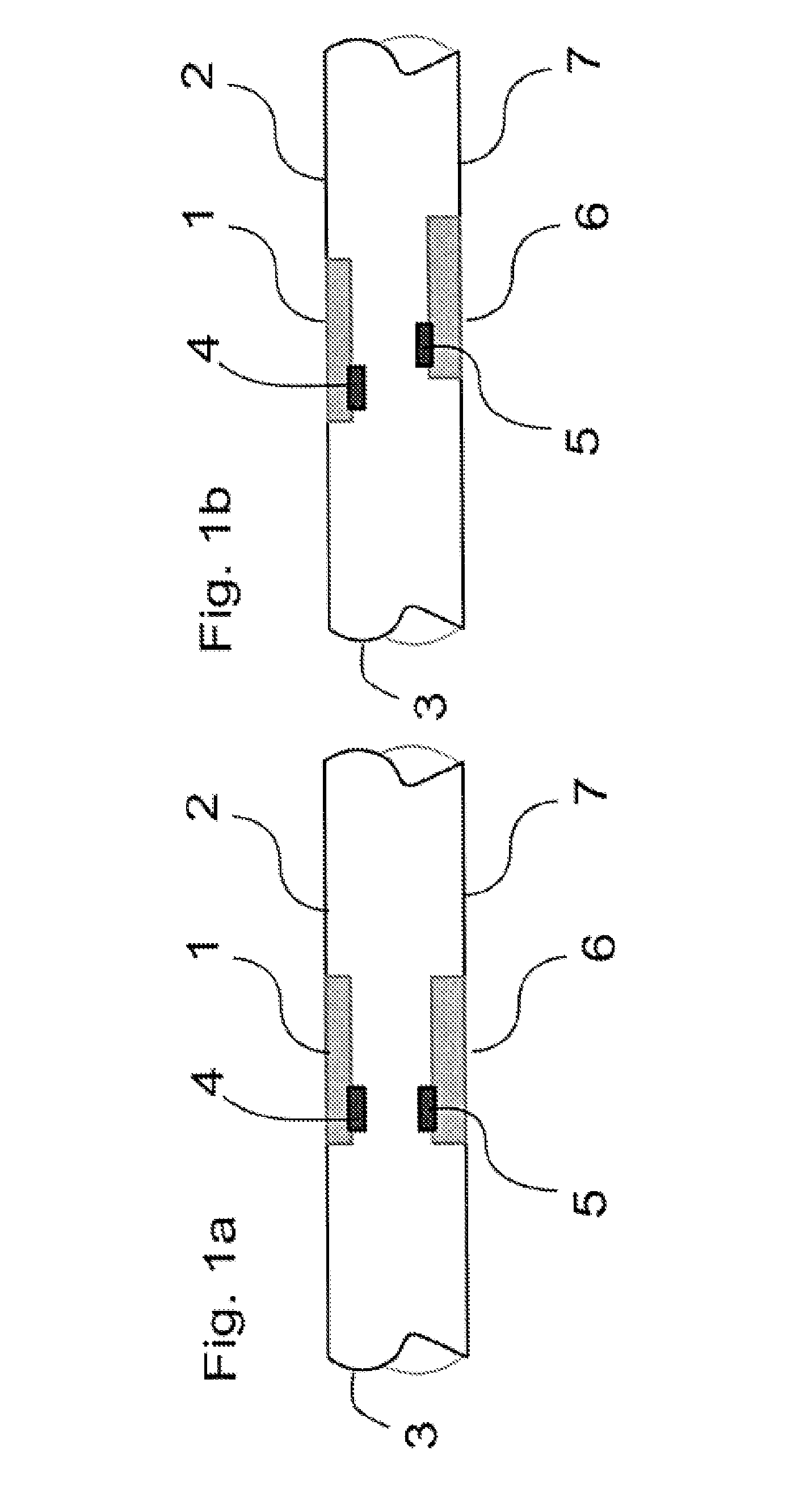
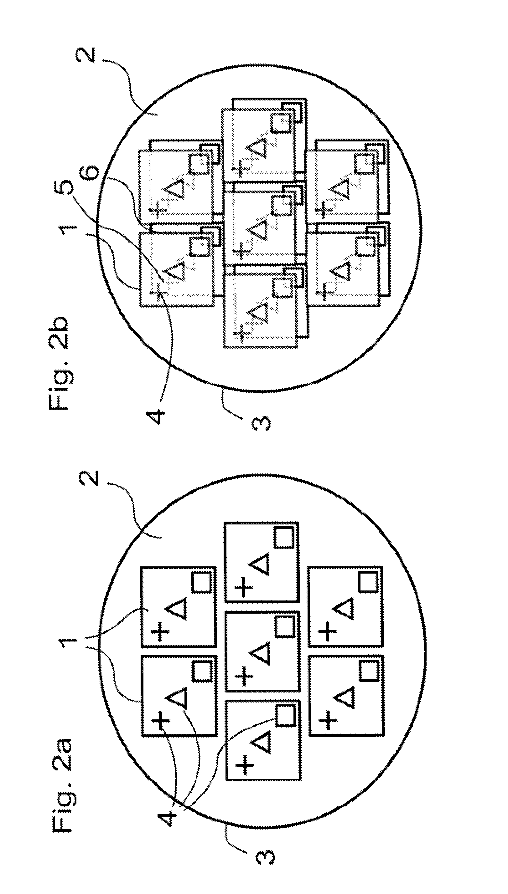
[0031]In FIGS. 1a and 1b, in each case a cross-section of a wafer 3 is shown as a substrate, which—as can also be seen in FIGS. 2a and 2b—has a large number of semiconductor components 1 on a top side 2 of the wafer 3 and a large number of semiconductor elements 6 on a bottom side 7 of the wafer 3.

[0032]Each semiconductor component 1, 6, designed here as dices 1, 6, has several contact points 4, 5, and the corresponding contact points 4 and 5 in each case are to be aligned exactly to one another, as shown in FIGS. 1a and FIG. 2a. In FIGS. 1b and 2b, the contact points 4 and 5, and the dices 1 and 6 are not correctly oriented, so that such a wafer 3 is scrap or has to be outfitted again at least on one side.

[0033]In the figures, the dices and the contact points are shown greatly enlarged, and a wafer with a 300 mm diameter has several hundred dices 1, 6, that in each case have several contact points 4, 5, which are shown only diagrammatically here for the sake of clarity. Each dice 1...


PUM


Abstract

In a system having a substrate holding means for holding a substrate, wherein the substrate holding means is rotatable about an axis of rotation that is perpendicular to an X-Y coordinate system, a method for determining position of the axis of rotation in the X-Y coordinate system, comprising the steps of:
    • providing a reference labeling on the substrate holding means or on the substrate;
    • determining a first X-Y reference position RP of a reference labeling on the substrate holding means or on the substrate by means of optical positional detecting means that is fixed relative to the X-Y coordinate system,
    • rotating the substrate holding means by a defined angle of rotation R around the axis of rotation,
    • determining by means of said fixed optical positional detecting means a second X-Y reference position RP′ of the reference labeling that is changed by the rotation, and
    • calculating the X-Y position of the axis of rotation in the substrate.

Description

FIELD OF THE INVENTION[0001]The invention relates to a method for determining an X-Y position in an X-Y coordinate system of an axis of rotation that is perpendicular to the X-Y coordinate system of a substrate holding means that can rotate around the axis of rotation for holding a substrate, and a method for determining a position of an axis of rotation R of the substrate in the substrate plane that is perpendicular to a substrate plane of a substrate. The invention further relates to a method for determining a position of an axis of rotation of the substrate holding means that is perpendicular to a substrate holding means plane of a substrate holding means for holding a substrate. The substrates of the present invention include semiconductors, preferably wafers, glass, quartz, ceramic and metal, and the application of a method to determine an orientation error of a large number of contact points oriented to one another and arranged on two opposite sides of a substrate.BACKGROUND O...

Claims


Application Information

Patent Timeline
IPC IPC(8): G01B11/00
CPCH01L21/67259G01B11/002H01L21/681H01L21/68H01L21/683H01L23/544
Inventor WAGENLEITNER, THOMAS
Owner EV GRP E THALLNER GMBH
Why Eureka
Try Eureka