
Storage tank for gaseous hydrogen

a technology for gaseous hydrogen and storage tanks, which is applied in the direction of packaging foodstuffs, packaged goods types, synthetic resin layered products, etc., can solve the problems of affecting the and affecting the weight and gravimetric efficiency of the tank

Pending Publication Date: 2022-04-14
ROLLS ROYCE PLC
View PDF0 Cites 0 Cited by
  • Summary
  • Abstract
  • Description
  • Claims
  • Application Information

AI Technical Summary

Benefits of technology

The patent describes a storage tank for gaseous hydrogen made using a special composite structure. The tank has a boundary wall made up of layers - a resin-rich layer, a glass-fibre composite layer, and a carbon fibre composite layer. The resin-rich layer is good at stopping gaseous hydrogen from leaking, while the glass-fibre composite layer is less likely to crack under pressure. The carbon fibre composite layer provides strength and stiffness to the tank. The tank can also have two layers of carbon fibre composite, with the second layer being stronger and more resistant to cracking. This helps to make the tank more durable and resistant to damage from high pressure hydrogen gas.

Problems solved by technology

Laminate composite gas storage tanks for automotive applications are too heavy for civil aviation applications, in which significantly greater volumes of hydrogen are needed than in automotive applications.
An automotive laminate composite gas storage tank typically comprises a polymer liner which contributes significantly to the tank's weight and therefore adversely affects its gravimetric efficiency.
The weight and gravimetric efficiency of such a tank are also compromised by the requirement that the tank be resistant to micro-cracking within its boundary wall as a result of pressure cycling.
Micro-cracking leads to leakage of stored gaseous hydrogen by permeation through the boundary wall of the tank.
Providing resistance to micro-cracking tends to result in laminate composite structures of substantial thickness and weight.
Although rapid consumption of gaseous hydrogen and a small number of pressure cycles allows for a lightweight tank within a spacecraft application, this design approach does not translate to civil aviation applications in which gaseous hydrogen is consumed at a much lower rate and in which a storage tank for gaseous hydrogen will experience many pressure and temperature cycles over its lifetime.

Method used


Image

  • Storage tank for gaseous hydrogen

Examples


Embodiment Construction

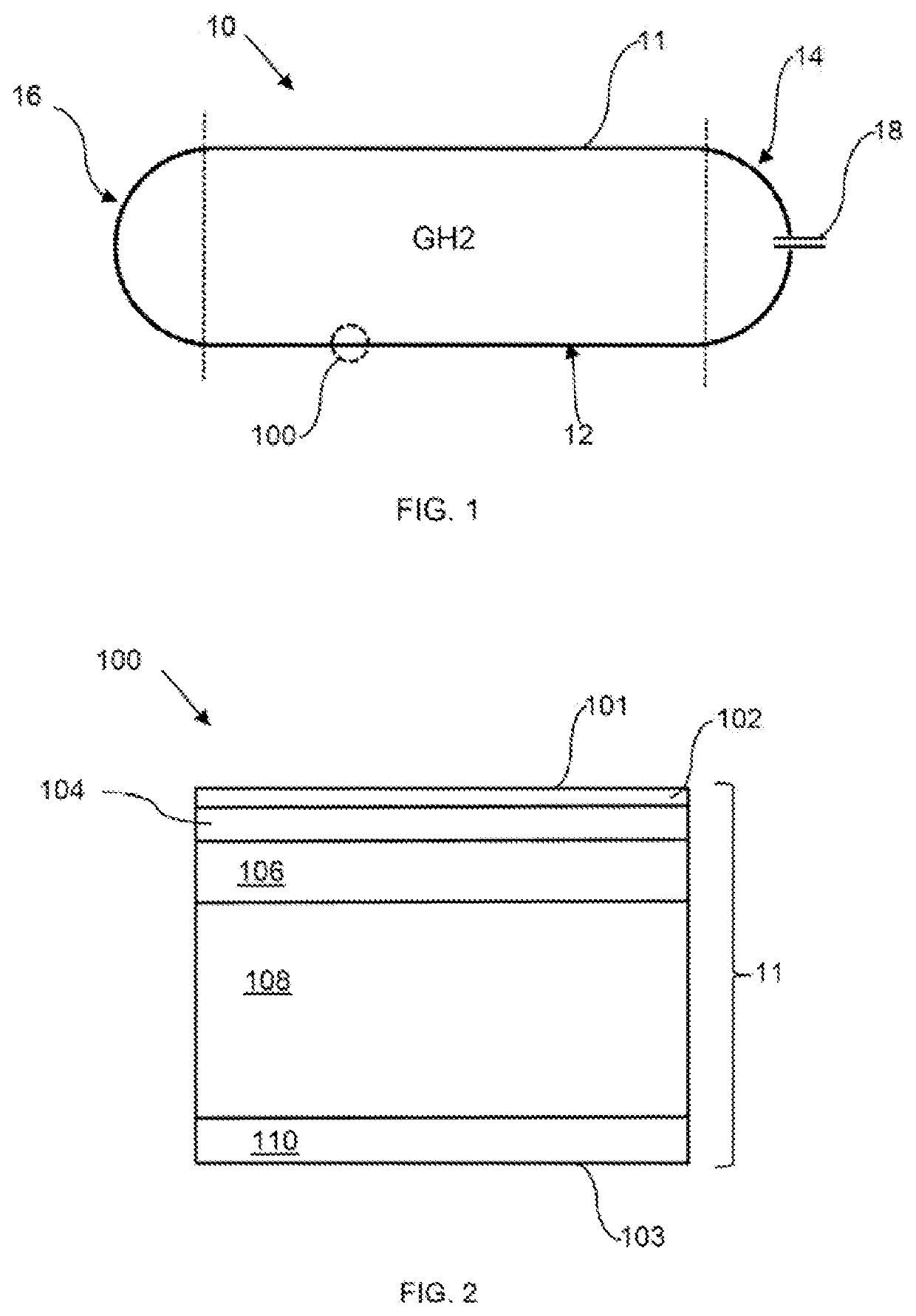
[0014]FIG. 1 shows a tank 10 for storage of gaseous hydrogen at high pressure, for example 300 bar or more. The tank 10 comprises a cylindrical central section 12 and two hemispherical end portions 14, 16 formed by a boundary wall 11. A metal fitting 18 passing through the boundary wall 11 at hemispherical end portion 14 allows filling and emptying of the tank 10.

[0015]FIG. 2 shows the structure of a portion 100 of the boundary wall 11 of the tank 10 of FIG. 1, the structure of the boundary wall 11 being substantially the same at all positions around the wall 11. The boundary wall 11 has a laminate composite structure and has inner and outer surfaces 101, 103 respectively. The inner most layer 102 of the boundary wall is a resin-rich layer which provides a high-quality layer which remains substantially free of void and cracks under pressure and temperature cycling and which therefore provides a layer of low permeability for hydrogen stored within the tank 10. The resin-rich layer 10...


PUM

PropertyMeasurementUnit
Thicknessaaaaaaaaaa
Electrical resistanceaaaaaaaaaa
Impermeabilityaaaaaaaaaa

Abstract

A storage tank for storing gaseous hydrogen comprises a boundary wall having a laminate composite structure which includes a resin-rich layer forming an internal surface of the boundary wall, a glass-fibre composite layer in contact with the resin-rich layer and a carbon fibre composite layer in contact with the glass-fibre composite layer on a side thereof remote from the resin-rich layer. The laminate structure provides a high level of hydrogen impermeability and resistance to micro-cracking as a result of pressure cycling, providing the tank with a gravimetric efficiency appropriate to aeronautical applications.

Description

CROSS-REFERENCE TO RELATED APPLICATIONS[0001]This application is based upon and claims the benefit of priority from British Patent Application No. 2016264.0, filed on Oct. 14, 2020, the entire contents of which are herein incorporated by reference.BACKGROUNDTechnical Field[0002]The disclosure relates to storage tanks for storing gaseous hydrogen, particularly at high pressure for example at 300 bar or more.Description of Related Art[0003]A laminate composite structure is a structure comprising a plurality of laminar layers at least one of which is of a composite material. A laminate composite gas storage tank is a gas storage tank in which the boundary wall of the tank has a laminate composite structure. Laminate composite gas storage tanks are currently used in automotive applications for storing gaseous hydrogen at high pressure. Motive power in these applications is typically provided by PEM fuel cells. Such tanks are also used in spaceflight applications and certain military dro...

Claims


Application Information

Patent Timeline
IPC IPC(8): F17C1/06
CPCF17C1/06F17C2221/012F17C2201/0109F17C2203/0663F17C2223/0123F17C2203/0604B32B5/26B32B27/12B32B2262/101B32B2262/106B32B2439/40B32B2307/50B32B25/10F17C1/00F17C2201/035F17C2223/036F17C2270/0189F17C2203/0621F17C2203/0624F17C2260/011F17C2203/0673F17C2260/012Y02E60/32B32B1/00F17C1/04
Inventor BACKHOUSE, ROBERT C.JAMES, DARREN
Owner ROLLS ROYCE PLC
Learn More