Method for manufacturing a wind power plant rotor blade

a technology for wind power plants and rotor blades, which is applied in the manufacture of final products, machines/engines, other domestic articles, etc., can solve the problems of time-consuming and laborious application of erosion protection to the surface and damage to the rotor blades of the wind power plant. achieve the effect of improving the erosion resistance of the rotor blad

Inactive Publication Date: 2021-07-29
WOBBEN PROPERTIES GMBH
View PDF0 Cites 0 Cited by
  • Summary
  • Abstract
  • Description
  • Claims
  • Application Information

AI Technical Summary

Benefits of technology

[0004]Provided is a method for manufacturing a wind power plant rotor blade that enables an improved erosion resistance of the rotor blade.
[0006]The use of a liquid erosion protection material makes it possible to better adjust the erosion protection material to the contours of the recess of the mold, The liquid material penetrates better even into complex contours of the recess of the mold, and ensures a better erosion protection even in complex contours. In addition, both air pockets and resin pockets can be avoided between the mold and erosion protection material. The liquid erosion protection material is likewise more process reliable, since the liquid erosion protection material cannot slip in the mold. The liquid erosion protection material further allows a faster, and hence more cost-effective, processing.
[0010]The method can thus be used to manufacture a wind power plant rotor blade, wherein an optimal erosion protection is achieved, in particular in the area of the rotor blade leading edge. An improved contour accuracy of the component can further be achieved, even after longer operation.

Problems solved by technology

Rotor blades of a wind power plant are constantly exposed to changing weather conditions, which can result in damage to the rotor blades of the wind power plant.
However, it is disadvantageous to use an erosion protection film that has to be adhesively bonded to the surface of the rotor blade afterwards, or to use a liquid erosion protection agent that must be applied to the surface of the rotor blade with rollers or brushes, because this can impair the aerodynamic surface of the rotor blade.
In addition, applying the erosion protection to the surface of the rotor blade is likewise time-intensive.

Method used


Image

  • Method for manufacturing a wind power plant rotor blade
  • Method for manufacturing a wind power plant rotor blade

Examples


Embodiment Construction

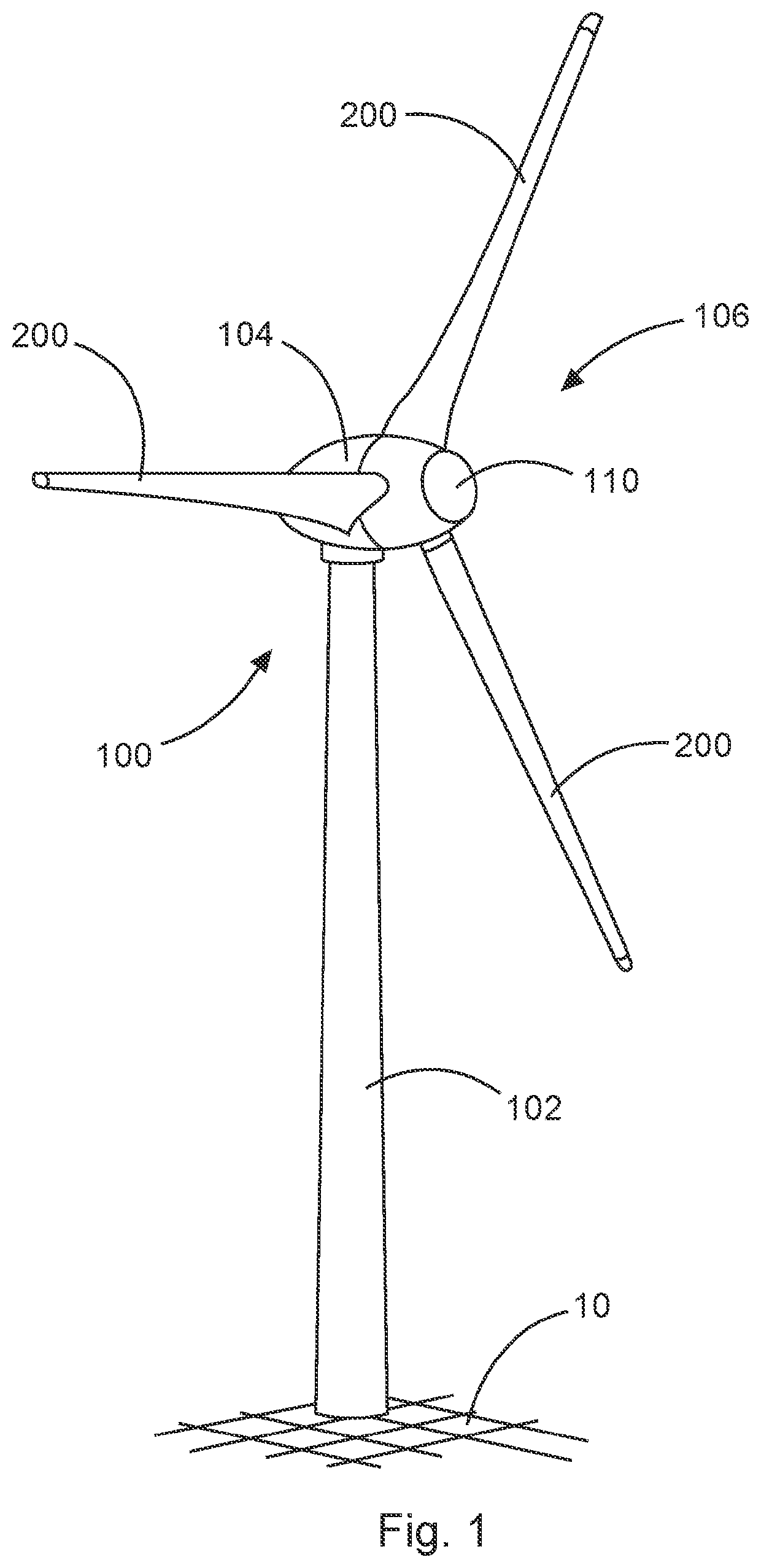
[0018]FIG. 1 shows a schematic illustration of a wind power plant according to an aspect of the present invention. The wind power plant 100 has a tower 102 and a nacelle 104 on the tower 102. An aerodynamic rotor 106 with three rotor blades 200 and a spinner 110 is provided on the nacelle 104. The aerodynamic rotor 106 is made to rotate by the wind during operation of the wind power plant, and thus also turns a rotor or runner of a generator, which is directly or indirectly coupled with the aerodynamic rotor 106. The electric generator is arranged in the nacelle 104, and generates electric energy. The pitch angles of the rotor blades 108 can be varied by pitch motors on the rotor blade roots 108b of the respective rotor blades 108.

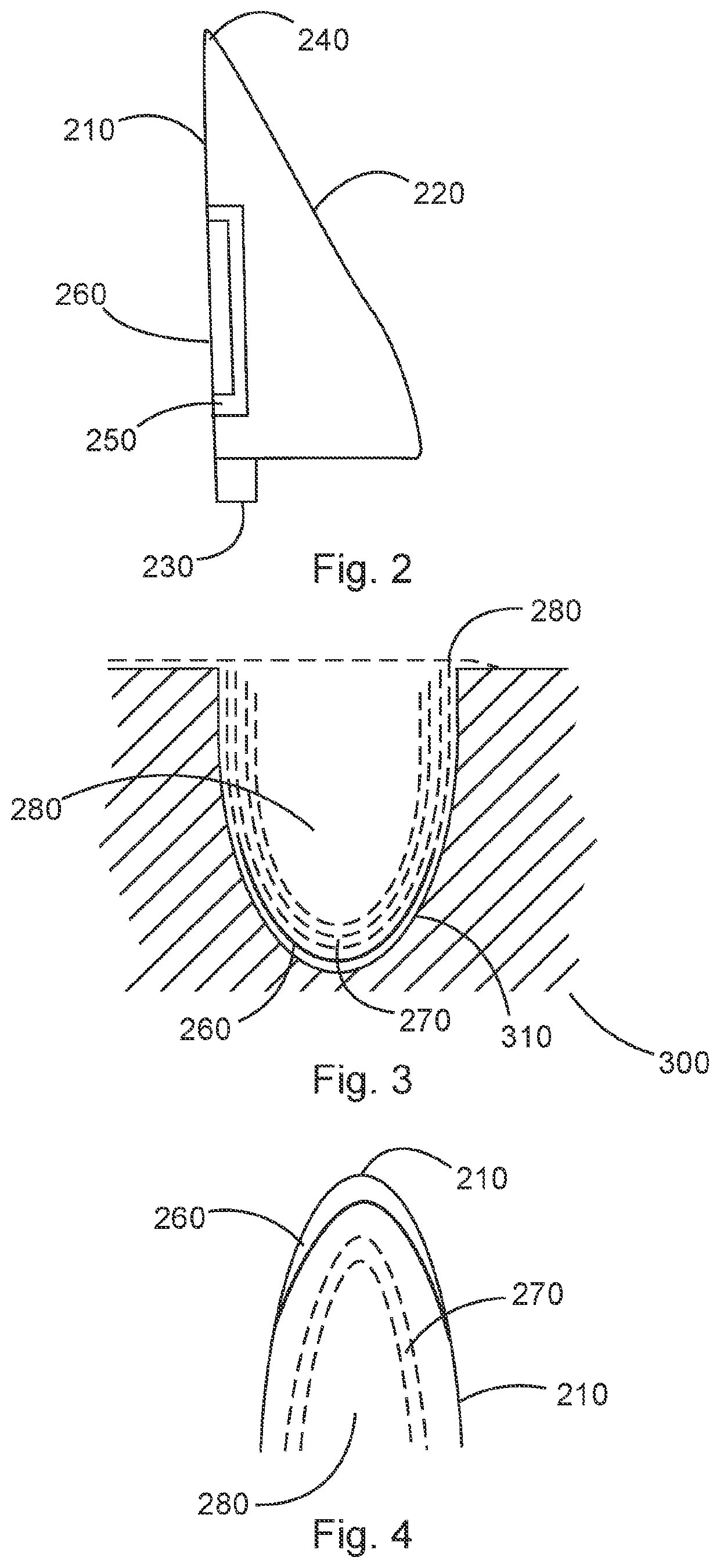
[0019]FIG. 2 shows a schematic illustration of a wind power plant rotor blade according to an aspect of the present invention. The rotor blade 200 has a rotor blade leading edge 210, a rotor blade trailing edge 220, a rotor blade root area 230 and a rotor ...


PUM

PropertyMeasurementUnit
timeaaaaaaaaaa
areaaaaaaaaaaa
aerodynamic surfaceaaaaaaaaaa

Abstract

A method for manufacturing a wind power plant rotor blade is provided. A mold for manufacturing at least a part of the wind power plant rotor blade is prepared. The mold has a recess, which is used to manufacture at least a part of the wind power plant rotor blade. Liquid erosion protection material is introduced into the recess. Fiber layers are placed in the recess of the mold after the liquid erosion protection material has at least partially hardened. A vacuum infusion bag or a vacuum infusion film is placed, and a vacuum infusion is performed with a resin, so as to obtain a composite component at least as part of the wind power plant rotor blade.

Description

BACKGROUNDTechnical Field[0001]The present invention relates to a method for manufacturing a wind power plant rotor blade as well as to a wind power plant rotor blade.Description of the Related Art[0002]Rotor blades of a wind power plant are constantly exposed to changing weather conditions, which can result in damage to the rotor blades of the wind power plant. In order to reduce damage to the rotor blades of the wind power plant, it is known to apply an erosion protection film to the surface of the rotor blade. Alternatively thereto, the rotor blade can be provided with erosion protection afterwards by applying an erosion protection material with rollers or brushes. However, it is disadvantageous to use an erosion protection film that has to be adhesively bonded to the surface of the rotor blade afterwards, or to use a liquid erosion protection agent that must be applied to the surface of the rotor blade with rollers or brushes, because this can impair the aerodynamic surface of t...

Claims


Application Information

Patent Timeline
Patent Type & Authority Applications(United States)
IPC IPC(8): F03D1/06B29C70/44
CPCF03D1/0675B29C70/443F05B2240/30B29L2031/085F05B2280/6013F05B2280/6003F05B2230/20F05B2280/5007B29C33/38B29C33/42B29C70/342B29C70/54F05B2240/303Y02E10/72Y02P70/50
Inventor BÄRTL, CHRISTINAVOIGT, KARSTEN
Owner WOBBEN PROPERTIES GMBH
Why Eureka
Try Eureka