Method and device for increasing solar cell output

Inactive Publication Date: 2013-08-22
LOGAN BRENT ELLIS
View PDF3 Cites 2 Cited by
  • Summary
  • Abstract
  • Description
  • Claims
  • Application Information

AI Technical Summary

Benefits of technology

This patent relates to a new technology for improving the efficiency of photovoltaic cells. It involves using angled reflectors to capture more light and direct it onto the cell surface, resulting in a greater amount of energy production. The patent describes various ways to enhance the reflector system, including the use of transparent covers, external coolingvanes, and embedded reflector lattice. The technology also takes into consideration the influence of temperature elevation and the importance of cell receptivity to low light levels. The overall effect of this patent is to create a more efficient photovoltaic system that captures more light and converts it into energy.

Problems solved by technology

The parallel reflector might be concave to intensify energy at the cell's surface provided the resulting temperature would not substantially decrease efficiency even with traditional heat sinks or external cooling vanes, however, a convex reflector could direct light more broadly, thereby conveying additional energy to the cell and adjacent reflectors without producing an excessive increase in temperature.

Method used


Image

  • Method and device for increasing solar cell output
  • Method and device for increasing solar cell output

Examples


Embodiment Construction

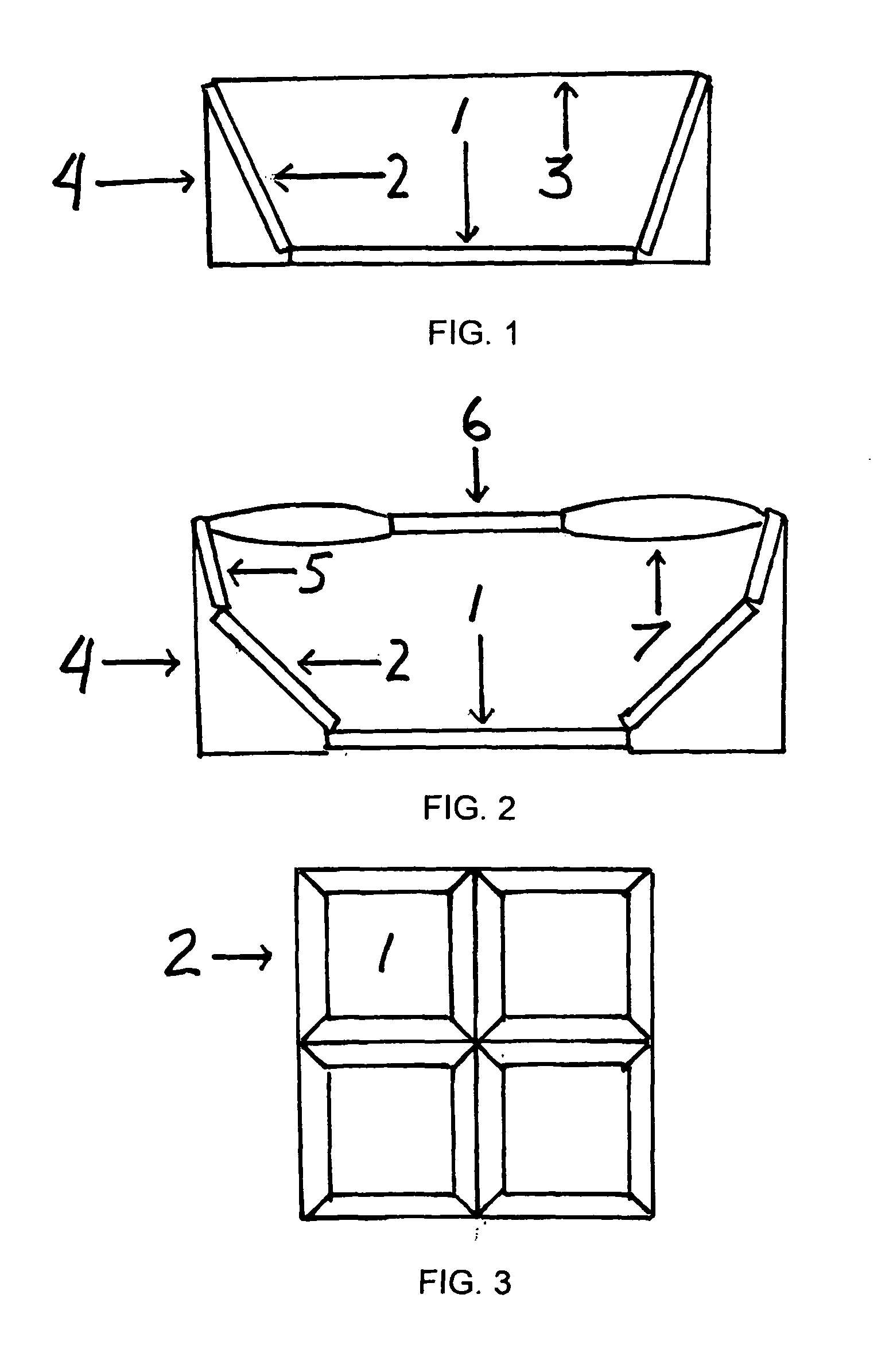
[0016]Referring to FIG. 1, one embodiment of the present innovation in a side perspective illustrates a photovoltaic cell, 1, surrounded by a single tier of reflectors, 2, protected by a transparent cover, 3, and supported in a frame, 4, which may also consist of cooling vanes.

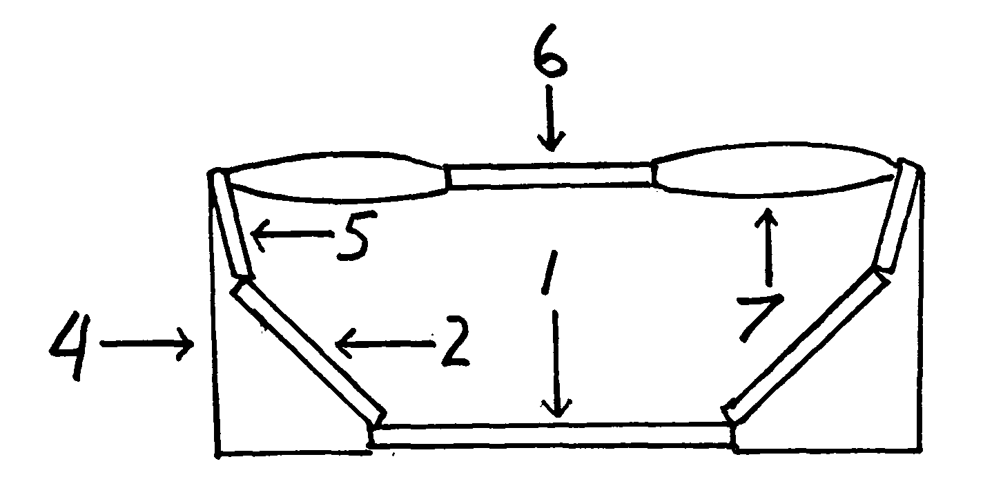
[0017]Referring to FIG. 2, another embodiment of the present innovation in a side perspective depicts a photovoltaic cell, 1, surrounded by a double tier of reflectors, 2 and 5, at different angles in relation to each other and the solar cell, supported in a frame, 4, with an overhead reflector, 6, and surrounding lens or lenses, 7, these also constituting a protective cover, 6.

[0018]Referring to FIG. 3, one embodiment of the present innovation viewed from an overhead perspective shows photovoltaic cells, 1, surrounded by a single tier of reflectors, 2, in a tessellated grid.


PUM


Abstract

To optimize photovoltaic energy in situ and without expensive heliostat systems, the power from full, diffracted, as well as low-angle sunlight can be significantly increased by utilizing flat or curved reflectors and / or lenses in any configuration around and / or above a solar cell, attached or independent, no matter the size or how situated, alone or multiply, with supports, heat sinks, or cooling vanes enclosed partly or entirely in a protective transparent envelope; enhanced photonic capture by this integrally reflective and modular CSP technology could with increased cell receptivity be further employed for nocturnal usage from stellar, lunar, and urban illumination as well as office, store, and household lighting both night and day.

Description

CROSS-REFERENCE TO RELATED APPLICATIONS [0001]This application claims the benefit of U.S. Provisional Patent Application No. 61 / 630,702 having a file date of Dec. 19, 2011, the primary contents of which are herewith incorporated by reference.REFERENCES CITED[0002]U.S. Patent Documents20060201498Sep. 14, 2006Olsson20090084375Apr. 2, 2009Xie7,952,057May 31, 2011Finot, et al.8,030,605Oct. 4, 2011Grassmann8,039,732Oct. 18, 2011Arkas, et al.8,063,300Nov. 22, 2011Horne, et al.STATEMENT REGARDING FEDERALLY SPONSORED RESEARCH OR DEVELOPMENT[0003]Not ApplicableREFERENCE TO SEQUENCE LISTING, A TABLE, OR A COMPUTER PROGRAM LISTING COMPACT DISK APPENDIX[0004]Not ApplicableBACKGROUND OF THE INVENTION[0005]According to the photoelectric effect, solar cells produce electrical energy that is proportionate to the amount of light energy falling upon them. By increasing the amount of light on a solar panel with adequate capacitance, it is possible to generate an equivalent multiple of electricity.[000...

Claims


Application Information

Patent Timeline
IPC IPC(8): H01L31/052
CPCH01L31/0524H01L31/0525Y02E10/52H01L31/0543H01L31/048H01L31/0547Y02B10/10
Inventor LOGAN, BRENT ELLIS
Owner LOGAN BRENT ELLIS
Why Eureka
Try Eureka