Sheet conveying apparatus and image forming apparatus
a conveying apparatus and forming apparatus technology, applied in mechanical conveyors, rolling carriages, thin material handling, etc., can solve the problems of degrading the precision of skew feed correction, conventional conveying apparatus as described above, and insufficient skew feed correction of thin sheets, etc., to suppress local deformation.
- Summary
- Abstract
- Description
- Claims
- Application Information
AI Technical Summary
Benefits of technology
Problems solved by technology
Method used
Image
Examples
first embodiment
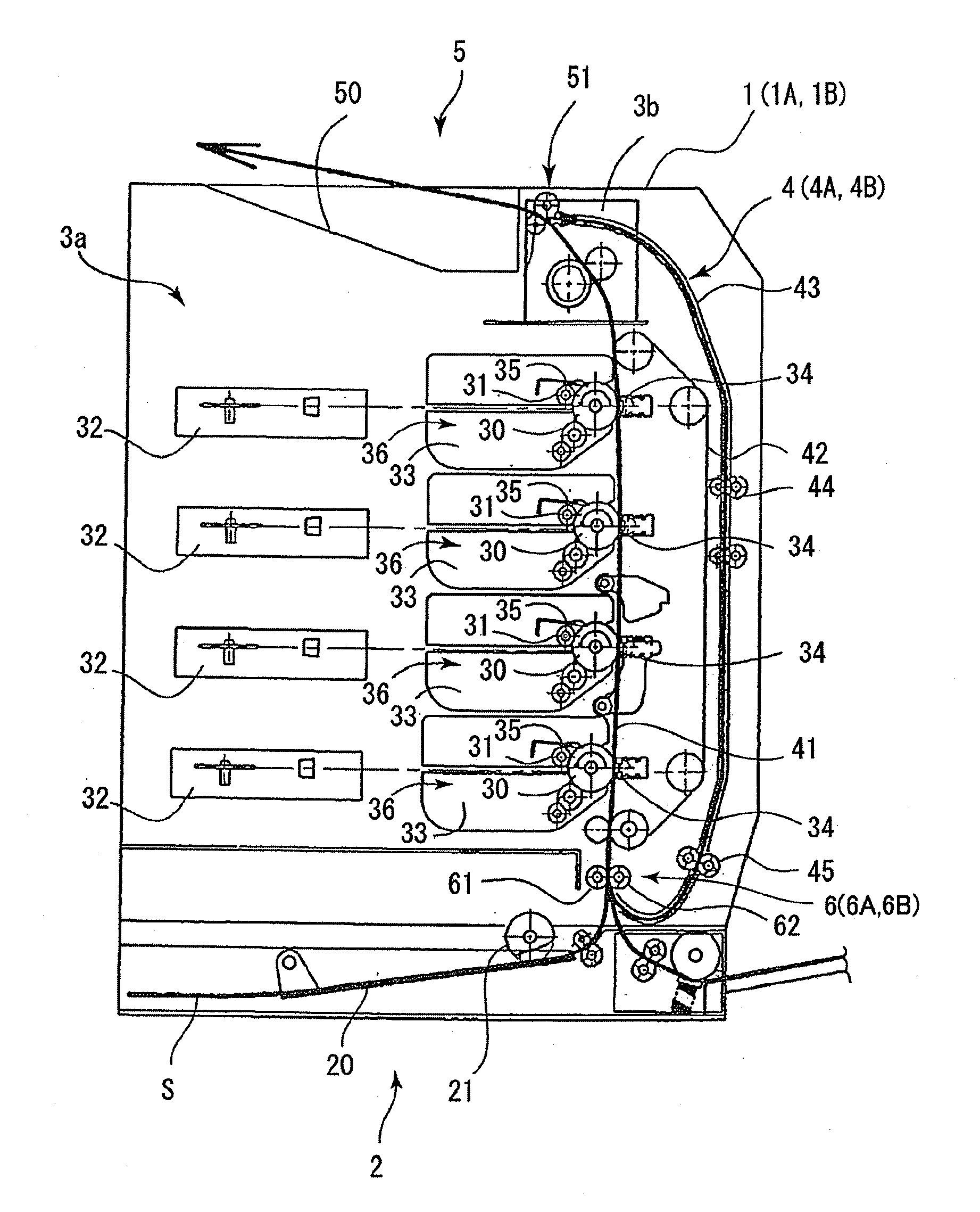
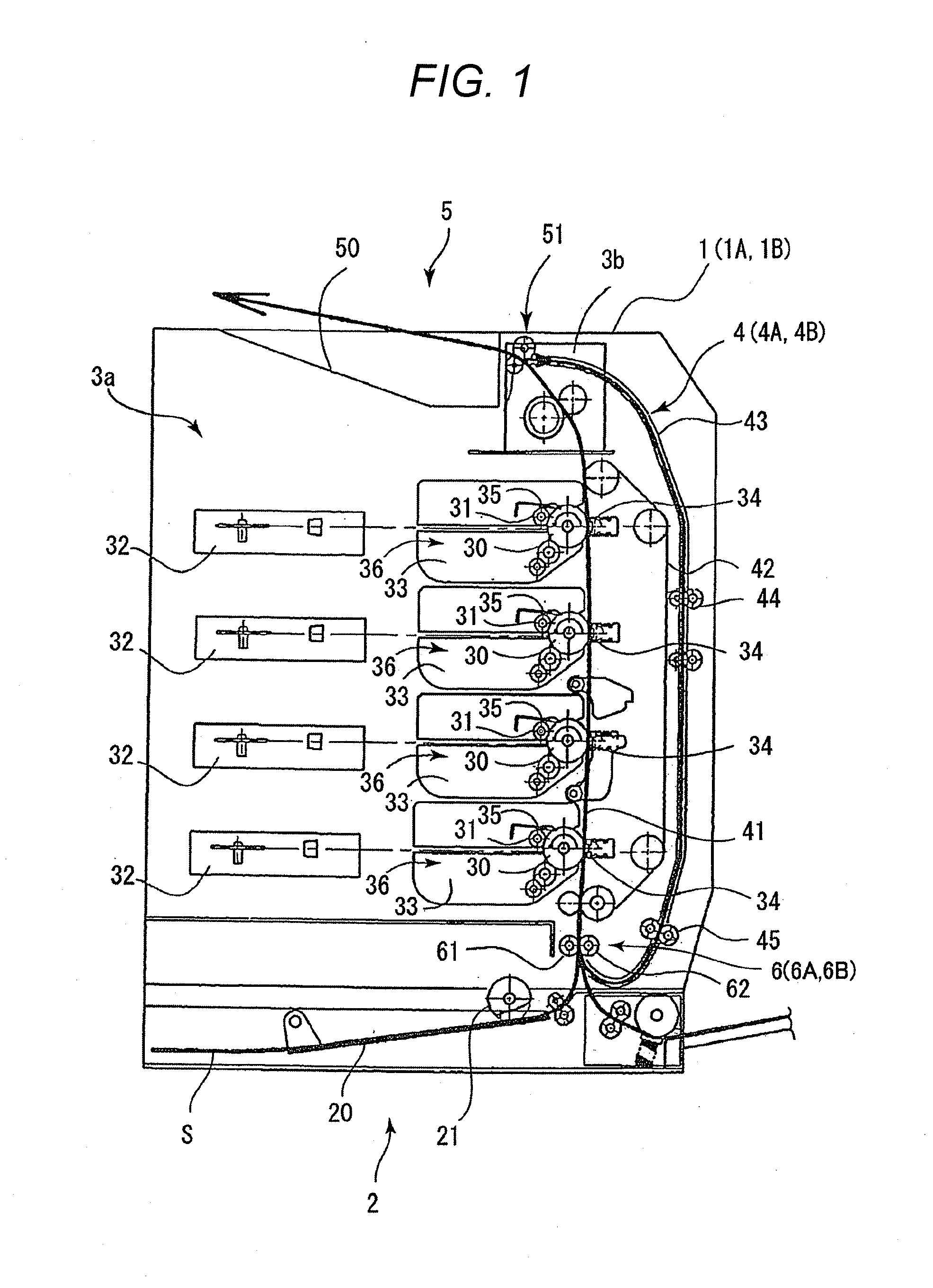
[0037]A laser beam printer 1 according to a first embodiment of the present invention will be described with reference to FIGS. 1 to 10. First, the entire structure of the laser beam printer 1 according to the first embodiment will be described with reference to FIG. 1. FIG. 1 is a cross-sectional view schematically illustrating the entire structure of the laser beam printer 1 according to the first embodiment of the present invention.
[0038]As illustrated in FIG. 1, the laser beam printer 1 according to the first embodiment includes a sheet feed portion 2 that feeds sheets S, an image forming portion 3a that forms an image, and a fixing portion 3b that fixes the image. The laser beam printer 1 further includes a sheet conveying portion 4 as a sheet conveying apparatus and a sheet discharge portion 5 that discharges the sheets S with images formed thereon.
[0039]The sheet feed portion 2 includes a feed cassette 20 in which the sheets S are contained, a feed roller 21 that feeds the sh...
second embodiment
[0080]Next, a laser beam printer 1A according to a second embodiment of the present invention will be described with reference to FIGS. 11 to 13B. FIG. 11 is a partially enlarged view illustrating a skew feed correcting portion 6A according to the second embodiment. FIG. 12 is a view illustrating a shutter portion 7A and a fixed guide portion 8A according to the second embodiment. FIG. 13A is a view schematically illustrating the shutter portion 7A in the first posture and the fixed guide portion 8A. FIG. 13B is a view schematically illustrating the state in which the sheet S is nipped by the nip portion as a result of the rotation of the shutter portion 7A.
[0081]The laser beam printer 1A according to the second embodiment is different from the laser beam printer 1 according to the first embodiment in the skew feed correcting portion in the sheet conveying portion. Therefore, in the second embodiment, the point different from the first embodiment, that is, the skew feed correcting p...
third embodiment
[0099]Next, a laser beam printer 1B according to a third embodiment of the present invention will be described with reference to FIGS. 14 to 17. FIG. 14 is a partially enlarged view illustrating a skew feed correcting portion 6B according to the third embodiment. FIG. 15 is a view illustrating a shutter portion 7A, a fixed guide portion 8B, and a swinging guide portion 9B according to the third embodiment. FIG. 16A is a view schematically illustrating the shutter portion 7A in the first posture. FIG. 16B is a view schematically illustrating a state in which the sheet S is nipped by the nip portion. FIG. 17 is a view illustrating a plurality of conveying postures of the sheet S that abuts against an abutment surface 74A of the shutter portion 7A according to the third embodiment.
[0100]The laser beam printer 1B according to the third embodiment is different from the laser beam printers 1 and 1A according to the first embodiment and the second embodiment in the skew feed correcting por...
PUM
 Abstract
Description
Claims
Application Information
 - R&D
- Intellectual Property
- Life Sciences
- Materials
- Tech Scout
- Unparalleled Data Quality
- Higher Quality Content
- 60% Fewer Hallucinations
Browse by: Latest US Patents, China's latest patents, Technical Efficacy Thesaurus, Application Domain, Technology Topic, Popular Technical Reports.
© 2025 PatSnap. All rights reserved.Legal|Privacy policy|Modern Slavery Act Transparency Statement|Sitemap|About US| Contact US: help@patsnap.com


