Sheet conveying apparatus and image forming apparatus

Active Publication Date: 2012-04-05
CANON KK
View PDF10 Cites 14 Cited by
  • Summary
  • Abstract
  • Description
  • Claims
  • Application Information

AI Technical Summary

Benefits of technology

[0007]It is an object of the present invention to provide a sheet conveying apparatus capable of correcting the skew of a sheet while sup

Problems solved by technology

However, the conventional sheet conveying apparatus as described above may not perform skew feed correction sufficiently with respect to a thin sheet.
As a result, the reaction force from the abutment portion is less

Method used


Image

  • Sheet conveying apparatus and image forming apparatus
  • Sheet conveying apparatus and image forming apparatus
  • Sheet conveying apparatus and image forming apparatus

Examples


first embodiment

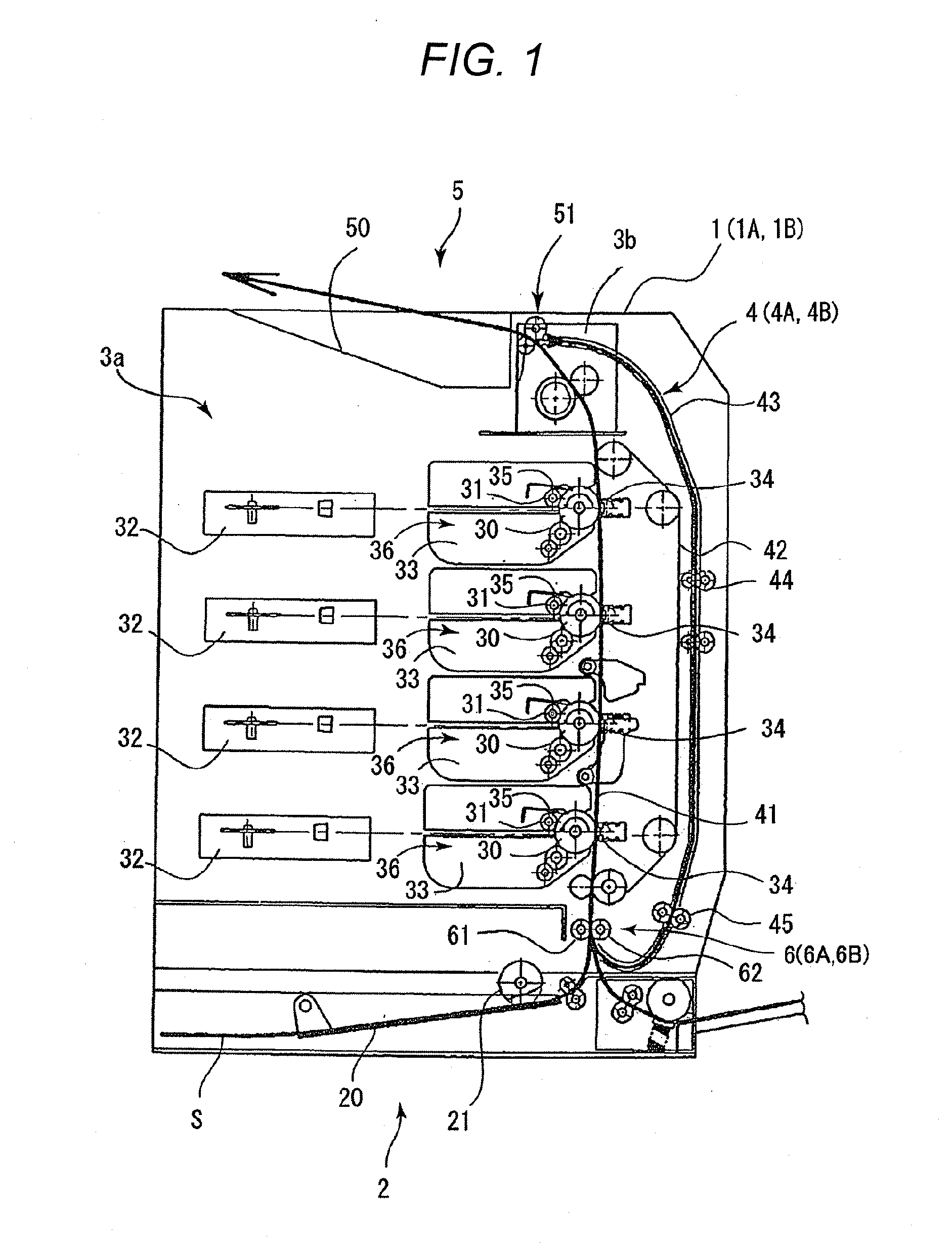
[0037]A laser beam printer 1 according to a first embodiment of the present invention will be described with reference to FIGS. 1 to 10. First, the entire structure of the laser beam printer 1 according to the first embodiment will be described with reference to FIG. 1. FIG. 1 is a cross-sectional view schematically illustrating the entire structure of the laser beam printer 1 according to the first embodiment of the present invention.

[0038]As illustrated in FIG. 1, the laser beam printer 1 according to the first embodiment includes a sheet feed portion 2 that feeds sheets S, an image forming portion 3a that forms an image, and a fixing portion 3b that fixes the image. The laser beam printer 1 further includes a sheet conveying portion 4 as a sheet conveying apparatus and a sheet discharge portion 5 that discharges the sheets S with images formed thereon.

[0039]The sheet feed portion 2 includes a feed cassette 20 in which the sheets S are contained, a feed roller 21 that feeds the sh...

second embodiment

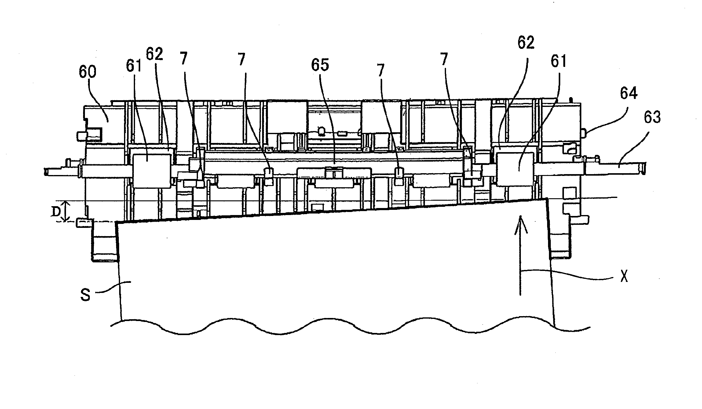
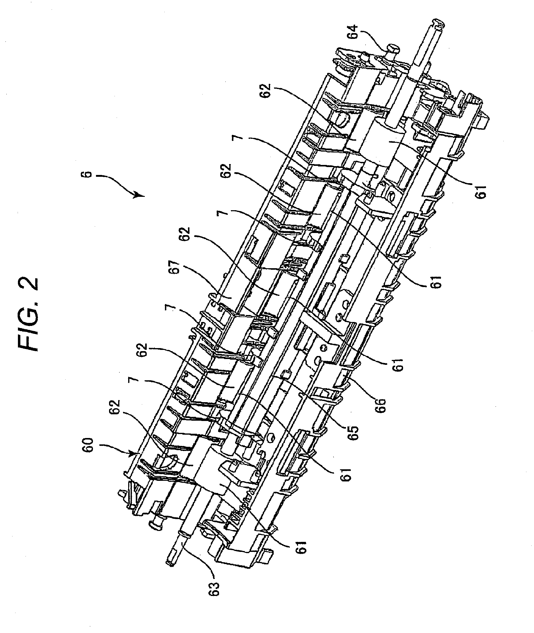
[0080]Next, a laser beam printer 1A according to a second embodiment of the present invention will be described with reference to FIGS. 11 to 13B. FIG. 11 is a partially enlarged view illustrating a skew feed correcting portion 6A according to the second embodiment. FIG. 12 is a view illustrating a shutter portion 7A and a fixed guide portion 8A according to the second embodiment. FIG. 13A is a view schematically illustrating the shutter portion 7A in the first posture and the fixed guide portion 8A. FIG. 13B is a view schematically illustrating the state in which the sheet S is nipped by the nip portion as a result of the rotation of the shutter portion 7A.

[0081]The laser beam printer 1A according to the second embodiment is different from the laser beam printer 1 according to the first embodiment in the skew feed correcting portion in the sheet conveying portion. Therefore, in the second embodiment, the point different from the first embodiment, that is, the skew feed correcting p...

third embodiment

[0099]Next, a laser beam printer 1B according to a third embodiment of the present invention will be described with reference to FIGS. 14 to 17. FIG. 14 is a partially enlarged view illustrating a skew feed correcting portion 6B according to the third embodiment. FIG. 15 is a view illustrating a shutter portion 7A, a fixed guide portion 8B, and a swinging guide portion 9B according to the third embodiment. FIG. 16A is a view schematically illustrating the shutter portion 7A in the first posture. FIG. 16B is a view schematically illustrating a state in which the sheet S is nipped by the nip portion. FIG. 17 is a view illustrating a plurality of conveying postures of the sheet S that abuts against an abutment surface 74A of the shutter portion 7A according to the third embodiment.

[0100]The laser beam printer 1B according to the third embodiment is different from the laser beam printers 1 and 1A according to the first embodiment and the second embodiment in the skew feed correcting por...


PUM


Abstract

A sheet conveying apparatus including: a conveying roller pair conveying a sheet by a nip portion; a shutter portion which is rotatably supported on a rotary shaft of the first conveying roller; a same radius portion, provided in the shutter portion, which is formed to have substantially the same radius as a radius of the first conveying roller; an abutment portion, provided in the shutter portion, and against which the leading edge of the sheet is abutted; and a boundary portion, provided in a boundary of the abutment portion and the same radius portion, which guides the leading edge of the sheet to the nip portion when the shutter portion is rotated by abutting the leading edge of the sheet against the boundary portion.

Description

BACKGROUND OF THE INVENTION[0001]1. Field of the Invention[0002]The present invention relates to a sheet conveying apparatus and an image forming apparatus including the same.[0003]2. Description of the Related Art[0004]In general, the accuracy of a recording position (hereinafter, also referred to as “recording precision”) of an image with respect to a sheet is one of the important factors from the viewpoint of keeping the quality in image formation. In order to enhance the recording precision in an image forming apparatus, when a sheet to be conveyed is skewed, it is necessary to correct the skewed sheet. Therefore, in conventional image forming apparatus, there have been proposed various sheet conveying apparatus having a skew feed correction function so as to enhance the recording precision.[0005]In the sheet conveying apparatus disclosed in Japanese Patent Application Laid-Open No. H09-183539, a plurality of conveying roller pairs are provided in a sheet width direction orthogo...

Claims


Application Information

Patent Timeline
IPC IPC(8): B65H5/06B65H9/00
CPCB65H5/062B65H5/26B65G13/02B65H9/06B65H9/004B65H9/14
Inventor OSADA, TAKEHITOKAWANISHI, MINORUWATANABE, KENJIFURUSAWA, MOTOHIRO
Owner CANON KK
Why Eureka
Try Eureka