Wireless power receiver and method of managing power thereof

Active Publication Date: 2013-08-22
LG INNOTEK CO LTD
View PDF23 Cites 56 Cited by
  • Summary
  • Abstract
  • Description
  • Claims
  • Application Information

AI Technical Summary

Benefits of technology

[0008]The disclosure provides a wireless power receiver capable of increasing the efficiency of the power transmission between a wireless power transmitter and the wireless power

Problems solved by technology

Although the commercialization of the electromagnetic induction technology has been rapidly progressed around small-size devices, the power transmission distance is short.
However, as the typical w

Method used


Image

  • Wireless power receiver and method of managing power thereof
  • Wireless power receiver and method of managing power thereof
  • Wireless power receiver and method of managing power thereof

Examples


Example

[0033]Hereinafter, the exemplary embodiments will be described with reference to accompanying drawings in detail so that those skilled in the art can easily realize the embodiments.

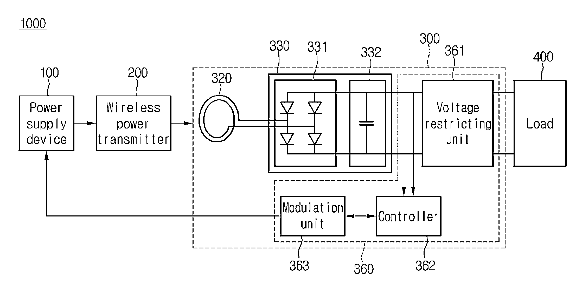
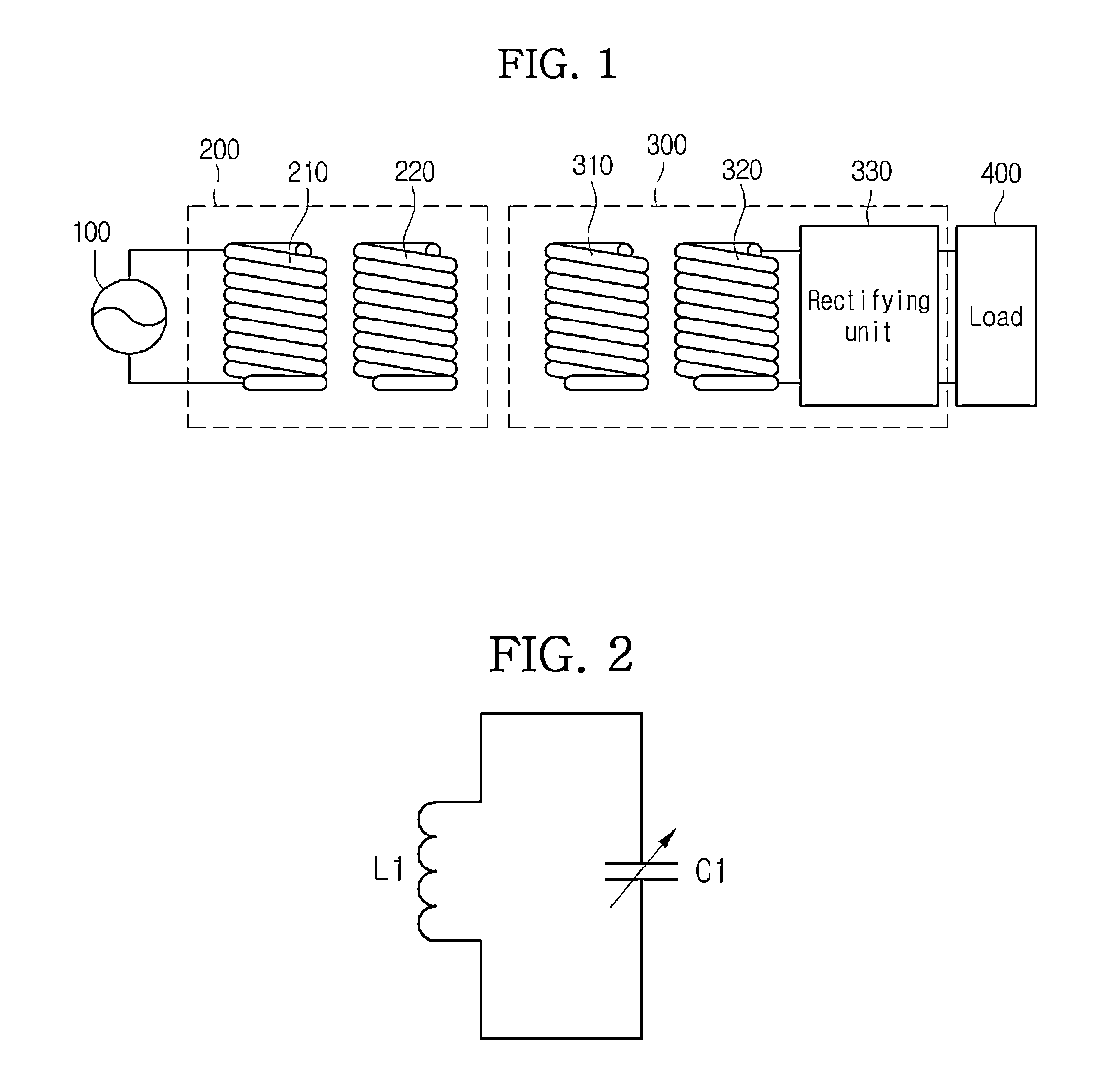
[0034]FIG. 1 a circuit diagram showing a resonance-type wireless power transmission system 1000 according to the embodiment.

[0035]Referring to FIG. 1, the wireless power transmission system 1000 may include a power supply device 100, a wireless power transmitter 200, a wireless power receiver 300 and a load side 400.

[0036]According to one embodiment, the power supply device 100 may be included in the wireless power transmitter 200.

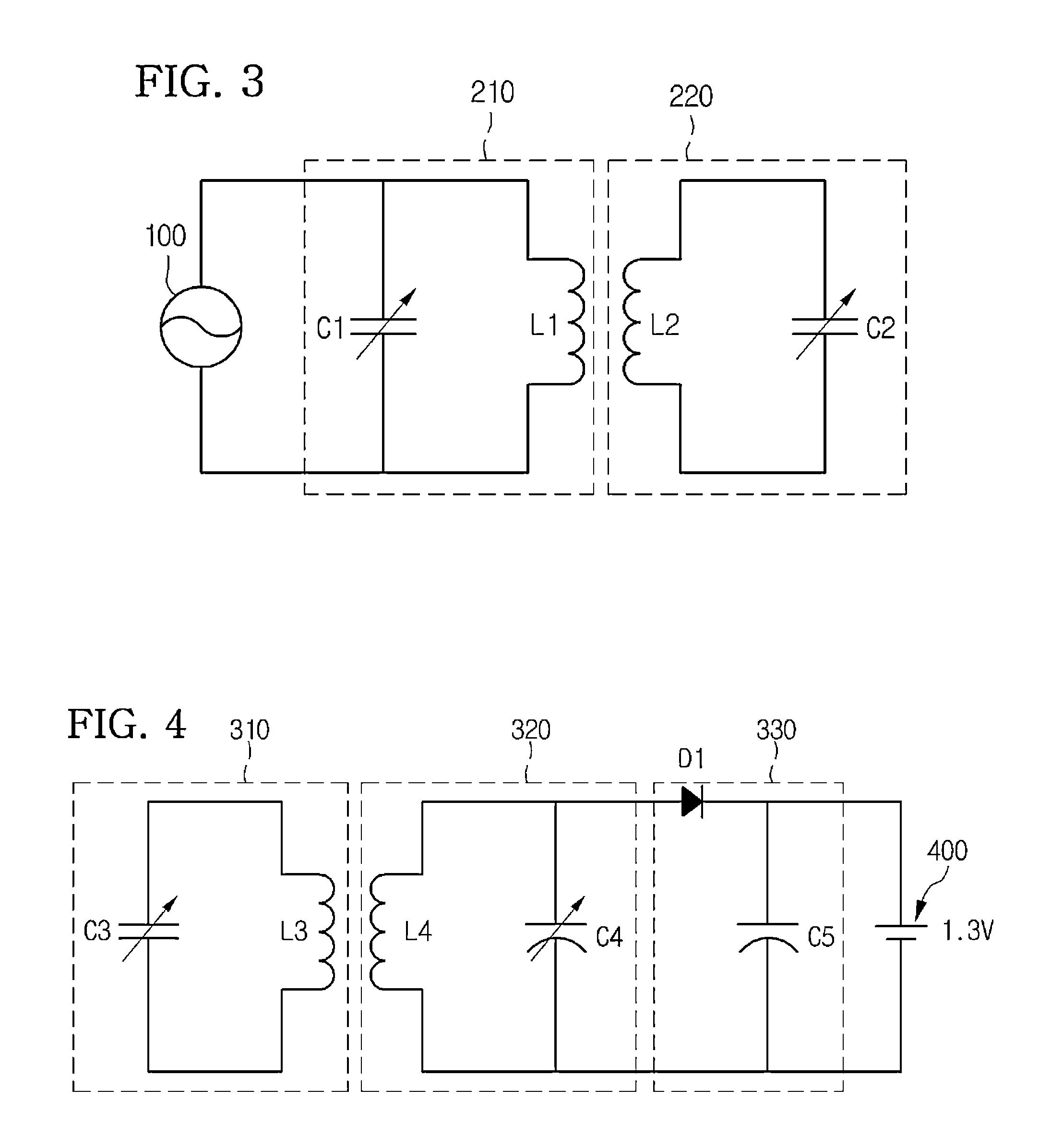
[0037]The wireless power transmitter 200 may include a transmission induction coil 210 and a transmission resonant coil 220.

[0038]The wireless power receiver 300 may include a reception resonant coil 310, a reception induction coil 320, and a rectifying unit 330.

[0039]Both terminals of the power supply device 100 are connected to both terminals of the transmission induction coil...


PUM


Abstract

Disclosed are a wireless power receiver and a method of managing the same. The wireless power receiver to wirelessly receive power from a wireless power transmitter and transmit the power to a load includes a receiving unit to receive AC power from the wireless power transmitter that receives power from a power supply device, a rectifying unit to rectify the received AC power to DC power, and a power managing unit to manage the power transmitted to the load based on the rectified DC power.

Description

CROSS-REFERENCE TO RELATED APPLICATIONS[0001]This application claims the benefit under 35 U.S.C. §119 of Korean Patent Application Nos. 10-2012-0017295, filed Feb. 21, 2012 and 10-2012-0022239, filed Mar. 5, 2012, which are hereby incorporated by reference in their entirety.BACKGROUND[0002]The disclosure relates to a wireless power transmission technology. In more particular, a wireless power receiver, capable of maximizing the power transmission efficiency in power transmission, and a method of managing the power thereof.[0003]A wireless power transmission or a wireless energy transfer refers to a technology of wirelessly transferring electric energy to desired devices. In the 1800's, an electric motor or a transformer employing the principle of electromagnetic induction has been extensively used and then a method for transmitting electrical energy by irradiating electromagnetic waves, such as radio waves or lasers, has been suggested. Actually, electrical toothbrushes or electrica...

Claims


Application Information

Patent Timeline
IPC IPC(8): H04B5/00H02M7/06
CPCH02M7/06H04B5/0037H04B5/0093H02J5/005H02M7/46H02J17/00H01F38/14H02J1/02H02J7/025H04B5/00H02J50/12H04B5/0087H02J7/00304H02J7/00308H02J50/80H02M1/14
Inventor BAE, SU HO
Owner LG INNOTEK CO LTD
Why Eureka
Try Eureka