Ceramic rotary valve for an anesthetic vaporizer

Inactive Publication Date: 2013-08-29
GE MEDICAL SYST GLOBAL TECH CO LLC
View PDF10 Cites 2 Cited by
  • Summary
  • Abstract
  • Description
  • Claims
  • Application Information

AI Technical Summary

Benefits of technology

The present invention provides a rotary valve for an anesthetic vaporizer made of ceramic material. The valve is used to control the concentration of anesthetics output from the vaporizer. The valve is designed to mix gas streams and control the concentration of anesthetics in the resulting mixture. This results in a more precise and accurate control of anesthesia delivery during surgery or medical procedures. The technical effect is improved control over anesthetic delivery for safer and more effective medical procedures.

Problems solved by technology

Since the rotary valve is a moving component, thousands of rotations will lead to surface wear and will directly affect the depth dimension of the spiral groove, which will eventually influence the output concentration.
However, the anesthetic vaporizing equipments described in these patents and the rotary valves used therein do not appropriately address the problem of the wearing of the valve surfaces.

Method used


Image

  • Ceramic rotary valve for an anesthetic vaporizer
  • Ceramic rotary valve for an anesthetic vaporizer
  • Ceramic rotary valve for an anesthetic vaporizer

Examples


Embodiment Construction

[0019]An embodiment of the present invention is now described in detail, an example of which is shown in the accompanying drawings. Reference numerals are used in the detailed description to indicate features in the drawings. Like numerals are used in the drawings and description to represent like features and components.

[0020]The following example is provided as an illustration of an embodiment of the invention, rather than a limitation of the invention. In fact, those skilled in the art will understand that modifications and alterations may be made to embodiments of the invention without departing from the scope and spirit of the invention. For example, a feature shown or described as a portion of an embodiment can be used in another embodiment, so as to yield yet another embodiment. Thus, embodiments of the present invention are intended to cover such modifications and alterations that come within the scopes of the appended claims and their equivalents.

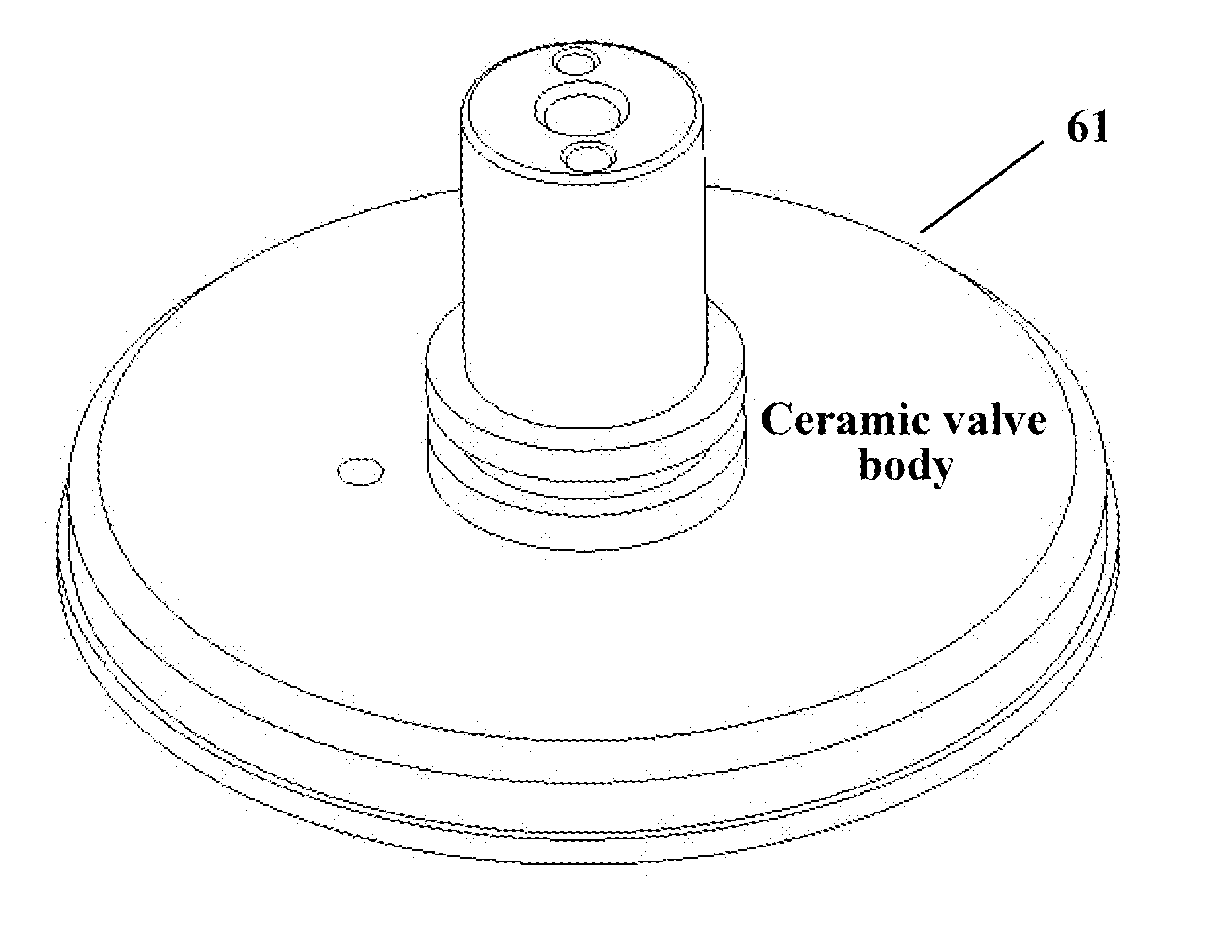
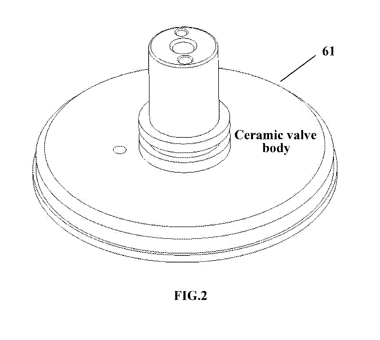
[0021]FIG. 2 illustrates an...


PUM


Abstract

Embodiments of the present invention relate to a ceramic rotary valve for an anesthetic vaporizer, the valve body of the rotary valve comprising a ceramic material. Embodiments of the present invention also provide an anesthetic vaporizer comprising the ceramic rotary valve and an anesthesia machine comprising the anesthetic vaporizer. Furthermore, embodiments of the present invention also provide a method of utilizing an anesthetic vaporizer comprising a ceramic rotary valve to control anesthetics concentration output by the anesthetic vaporizer.

Description

BACKGROUND OF THE INVENTION[0001]Embodiments of the present invention relate to an anesthetic vaporizer, and more particular, to a rotary valve for the anesthetic vaporizer.[0002]An anesthesia machine is a medical apparatus commonly used in clinical operation, which is used for delivering anesthetics into a patient body via mechanical circuit and finally implementing anesthesia on the patient. An anesthesia machine mainly comprises such components as a gas supply and delivery system, an anesthetic vaporizer, a respirator, a monitoring and controlling system, and so forth. As a key component of the anesthesia machine, the vaporizer is used for transforming anesthetics into vapor, and utilizing a certain amount of carrier gas to obtain anesthetic gas with a certain concentration. A valve (for example, a rotary valve) is typically used in the vaporizer to control the concentration of anesthetics output therefrom.[0003]A structural illustration of an anesthetic vaporizer is shown in FIG...

Claims


Application Information

Patent Timeline
IPC IPC(8): A61M16/01
CPCA61M16/01A61M16/20A61M16/18
Inventor GU, HONGKUITAN, BIN
Owner GE MEDICAL SYST GLOBAL TECH CO LLC
Why Eureka
Try Eureka