Fast charge stations for electric vehicles in areas with limited power availabilty

a technology for electric vehicles and charging stations, applied in charging stations, electric vehicle charging technology, transportation and packaging, etc., can solve the problems of prohibitive penetration into areas with lesser power availability, prohibitive rate structures including peak demand charges, and often considerable civil engineering and architectural involvement in stations

Inactive Publication Date: 2013-08-29
PROTERRA INC
View PDF15 Cites 65 Cited by
  • Summary
  • Abstract
  • Description
  • Claims
  • Application Information

AI Technical Summary

Benefits of technology

[0006]In some embodiments, the charging station may be used in a folly buffered energy transfer process, where the vehicle energy storage system may charged via the stationary energy storage system, which is being charged by the external energy source via the slow charger. in some other embodiments, the charging station may be used in a partially buffered energy transfer process, where the vehicle energy storage system may be charged via the stationary energy storage system and the external energy source via the slow charger, where the external energy source normally charges the stationary energy storage system except when the vehicle energy storage system is being charged. In some embodiments, the charging station may have a controller which may selectively control the slow charger to permit the charging of the stationary energy storage system and / or the rate of charging the stationary energy storage system. In some instances, the controller may determine whether the external energy source is used to charge the vehicle energy storage system or the stationary energy storage system.

Problems solved by technology

Despite access to adequate power, implementation of such stations often requires considerable civil engineering and architectural involvement to integrate with the grid.
However, the high current draw and civil engineering requirements make penetration into areas with lesser power availability prohibitive.
Additionally, rate structures which include peak demand charges can be prohibitive from a cost perspective at 6 C rates regardless of access to high voltage transmission lines.

Method used


Image

  • Fast charge stations for electric vehicles in areas with limited power availabilty
  • Fast charge stations for electric vehicles in areas with limited power availabilty
  • Fast charge stations for electric vehicles in areas with limited power availabilty

Examples


Embodiment Construction

[0020]While preferable embodiments of the invention have been shown and described herein, it will be obvious to those skilled in the art that such embodiments are provided by way of example only. Numerous variations, changes, and substitutions will now occur to those skilled in the art without departing from the invention. It should be understood that various alternatives to the embodiments of the invention described herein may be employed in practicing the invention.

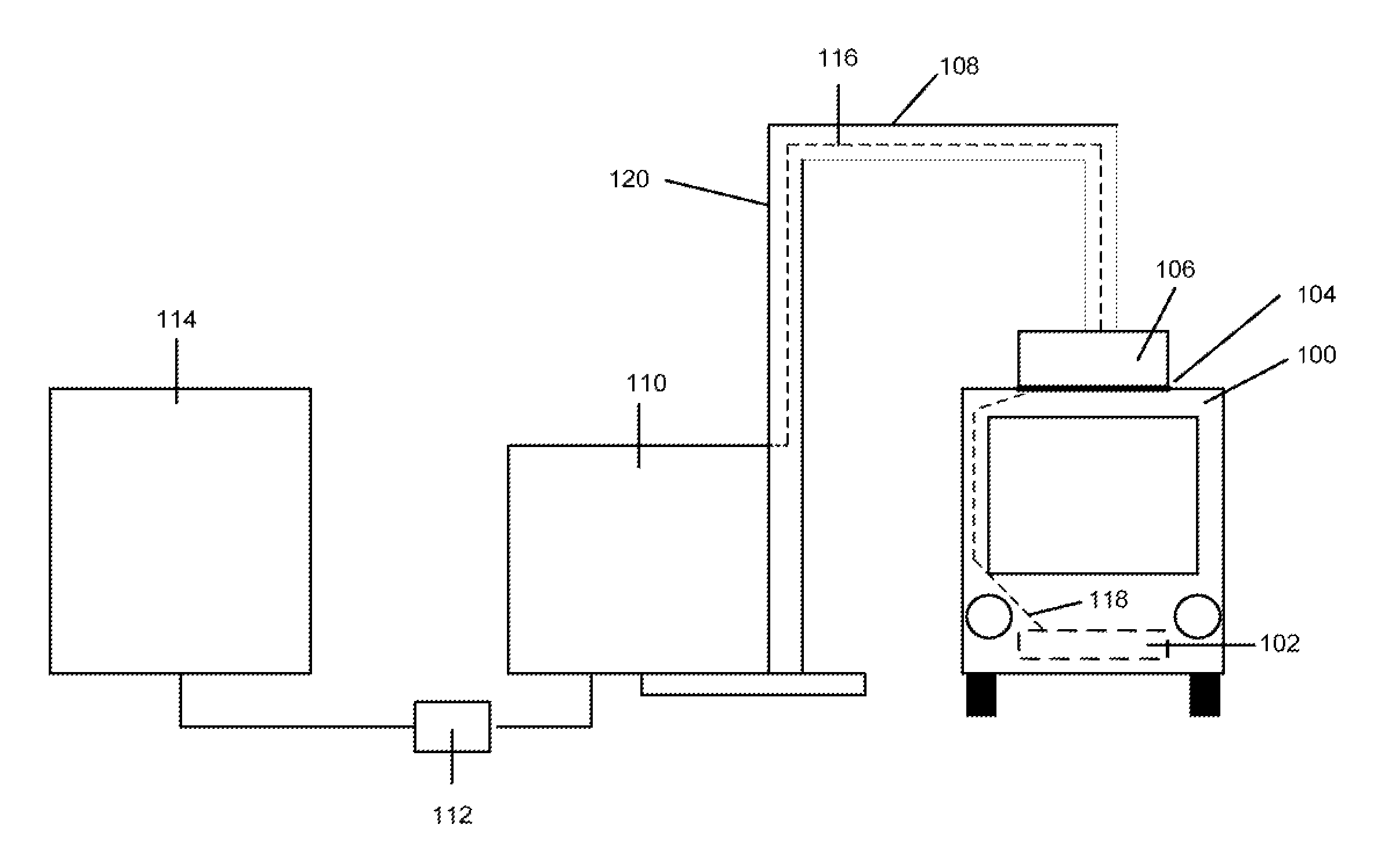
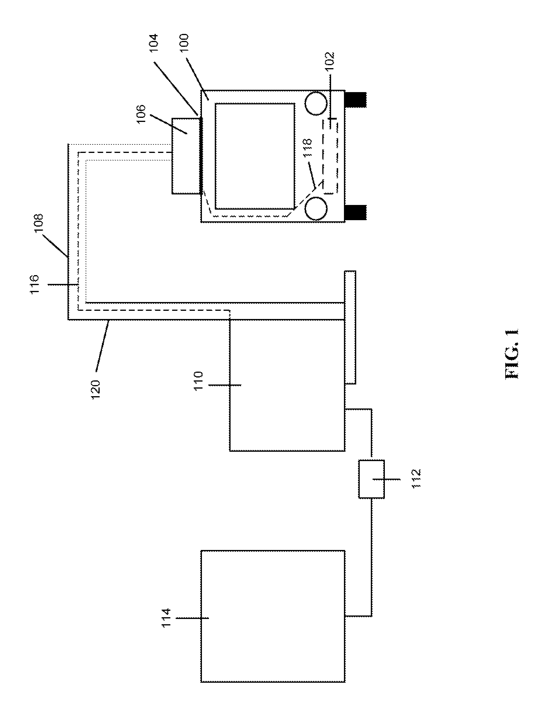
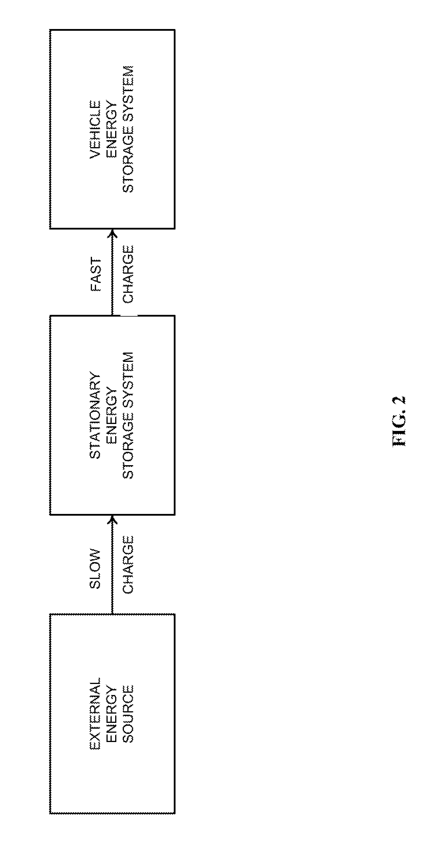
[0021]An aspect of the invention may involve either fully or partially buffering a fast. charge process with an upstream energy storage system connected to a slower rate charger. Instead of connecting the fast charger hardware directly to an external energy source, such as the grid, it may be connected to a stationary energy storage system. This energy storage system may in turn be connected to a slow rate charger that may plug into the grid most likely via a conventional power receptacle. Under this configuration the s...


PUM


Abstract

Systems and methods for charging a vehicle are provided. Electric or hybrid electric vehicles may be charged in areas with limited power availability or in situations where a gradual draw of power from an external energy source is desired. The external energy source may be used to charge a stationary energy storage system at a first rate, and the stationary energy storage system may be used to charge the vehicle energy storage system at a second rate. Preferably, the second rate may be greater than the first rate.

Description

CROSS-REFERENCE[0001]This application claims the benefit of U.S. Provisional Application No. 61 / 328,143, tiled Apr. 2, 2010, which application is incorporated herein by reference in its entirety.BACKGROUND OF THE INVENTION[0002]Charging stations for electric vehicles, particularly with rapid charge rates of 6 C or greater, may pose a concern when used in areas with limited power availability, such as residential or areas powered by wind or solar, or in areas where high peak demand charges apply. Current fast charge station deployments are taking place in areas with access to 12 kV high voltage transmission lines where the 440 volt, 3Ø, 1000 or more amp draw for 5-10 minutes is less problematic. Despite access to adequate power, implementation of such stations often requires considerable civil engineering and architectural involvement to integrate with the grid. However, the high current draw and civil engineering requirements make penetration into areas with lesser power availabilit...

Claims


Application Information

Patent Timeline
Patent Type & Authority Applications(United States)
IPC IPC(8): B60L11/18
CPCB60L11/1837B60L11/185B60L2200/18Y02T10/6269Y02T90/121Y02T90/128Y02T90/14B60L11/1824Y02T10/7005Y02T10/7072H02J7/34B60L53/32B60L53/11B60L53/302Y02T10/62Y02T90/12Y02T10/70
Inventor HILL, DALESARKAR, REUBENGALLEGOS, NICKY G.FINNERN, MICHAEL ALAN
Owner PROTERRA INC
Why Eureka
Try Eureka