Microscope and method for wavelength-selective and high spatial resolving microscopy

Active Publication Date: 2013-08-29
CARL ZEISS MICROSCOPY GMBH
View PDF10 Cites 7 Cited by
  • Summary
  • Abstract
  • Description
  • Claims
  • Application Information

AI Technical Summary

Benefits of technology

[0022]The localization can he made easier if the spectrally selective element has a central area lying on the optical axis which central area has broadband spectral transmission properties and is surrounded by sectors which differ from each other and preferably also horn the central area in respect of their spectral transmission properties. In the central area, the diffraction-limited point image of each fluorescence emitter is t

Problems solved by technology

The PALM method therefore usually requires a large number of frames, which means that it takes a certain period of time to record a complete image.
However, a disadvantage of this design is that the camera systems used are very expensive due to the high resolution required.
The cameras are also usually cooled and likewise require a large installation space, further proble

Method used


Image

  • Microscope and method for wavelength-selective and high spatial resolving microscopy
  • Microscope and method for wavelength-selective and high spatial resolving microscopy
  • Microscope and method for wavelength-selective and high spatial resolving microscopy

Examples


Example

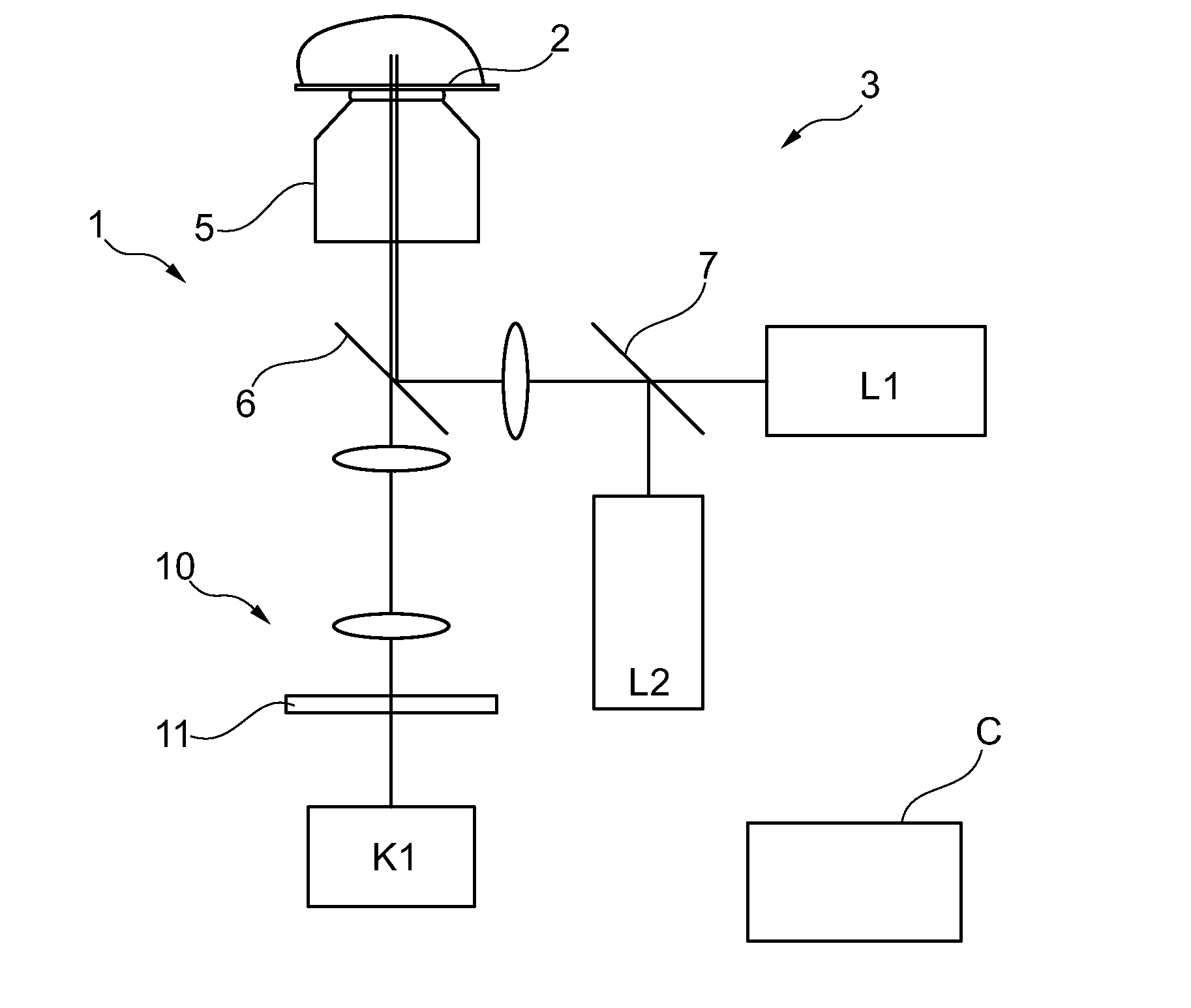
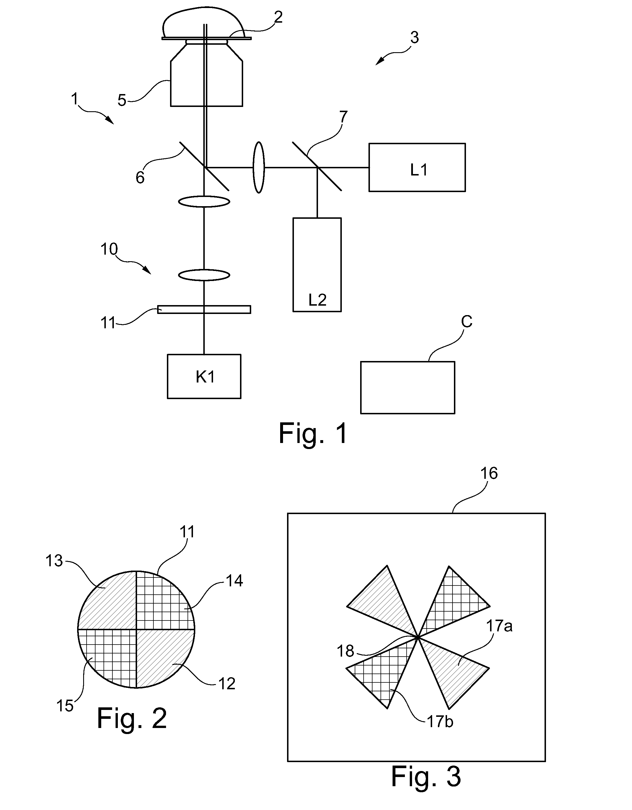
[0035]FIG. 1 schematically shows a fluorescence microscope 1 the operation of which is controlled by a control device C. The control device is connected to the elements of the microscope 1 via connections that are not shown, in particular to laser source(s) and camera. Elements or components which correspond functionally and / or structurally to elements or components which have already been explained with reference to the microscope 100 of FIG. 8, thus in respect of their function or structure correspond to the state of the art, are provided with the same reference numbers in the representation of FIG. 1 Their description therefore need not be repeated.

[0036]The microscope 1 of FIG. 1 comprises, in addition to the illumination beam path 3, an imaging beam path 10 which, however, as will he explained later, functions without spectral division into several colour channels. Therefore, only a single camera K1 is required. The imaging of the specimen is guided through a spectrally selecti...


PUM


Abstract

A method for wavelength-selective and high spatial resolving fluorescence microscopy. In a specimen fluorescence emitters are repeatedly excited and specimen frames are produced with a microscope. The fluorescence emitters are excited to emit fluorescence radiation such that at least a sub-set is isolated in each frame and the positions of the isolated fluorescence emitters are localized with a localization precision exceeding the optical resolution and a high-resolution complete image is produced. The imaging beam path of the microscope has a spectrally selective element which, during production of the frames, generates a spectrally-dependent rotational asymmetric point-spread function, such that images of isolated fluorescence emitters have a rotational asymmetry which depends on a wavelength at which the isolated fluorescence emitters fluoresce, and the images of the isolated fluorescence emitters are analysed with respect to rotational asymmetry and an indication of the wavelength of the isolated fluorescence emitters is derived therefrom.

Description

PRIORITY CLAIM[0001]The present application claims priority to DE application no. 102012201286.9, filed Jan. 30, 2012, entitled MICROSCOPE AND METHOD FOR WAVELENGTH-SELECTIVE AND HIGH SPATIAL RESOLVING MICROSCOPY, which is incorporated by reference herein in its entirety.BACKGROUND OF THE INVENTION[0002]Various methods of braking the diffraction limit in microscopy have been developed in the state of the art. A method abbreviated to PALM (photo activated light microscopy) is known from WO 2006 / 127692 or DE 102006021317 A1, which uses a label substance for imaging a specimen which can be activated e.g. by means of optical radiation. Only in the activated state can the label substance emit specific fluorescence radiation. Non-activated molecules of the label substance emit no, or at least no noticeable, fluorescence radiation even after irradiation by excitation radiation. The activation radiation is therefore generally called a switching signal. In the PALM method, the switching sign...

Claims


Application Information

Patent Timeline
IPC IPC(8): G01N21/64
CPCG01N21/6458G02B21/16G01N21/64G02B27/58G02B21/365
Inventor KALKBRENNER, THOMASWOLLESCHENSKY, RALF
Owner CARL ZEISS MICROSCOPY GMBH
Why Eureka
Try Eureka