Solid electrolytic capacitor

Active Publication Date: 2013-08-29
PANASONIC CORP
View PDF7 Cites 8 Cited by
  • Summary
  • Abstract
  • Description
  • Claims
  • Application Information

AI Technical Summary

Benefits of technology

[0014]As described above, according to the present invention, the cathode terminal is provided with the cathode support portion that is brought into contact with the lower surface on an end portion side of the cathode portion without involving the conductive adhesive therebetween. An upper end portion of the cathode support portion prevents a lower surface on an end portion side of the cathode portion of a capacitor element from inclining downwardly. Accordingly, it is possible to reliably cover the end portion of the cathode portion of the capa

Problems solved by technology

As a result, this causes a problem such as

Method used


Image

  • Solid electrolytic capacitor
  • Solid electrolytic capacitor
  • Solid electrolytic capacitor

Examples


Example

[0022]A solid electrolytic capacitor according to an embodiment of the present invention will be described.

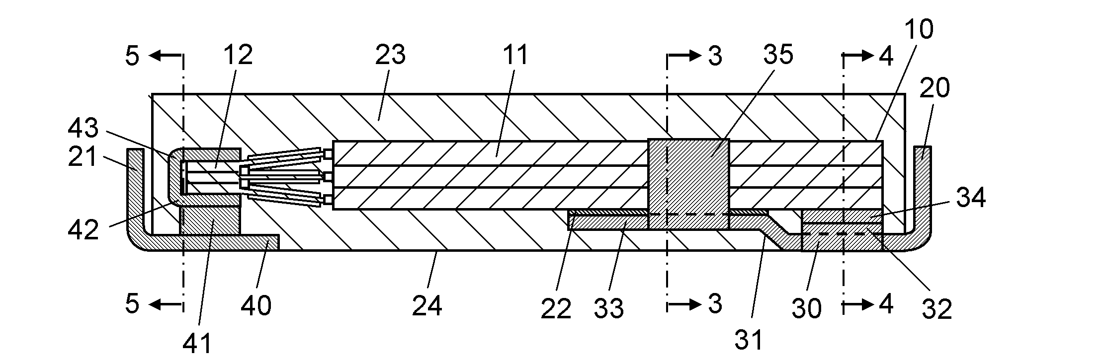
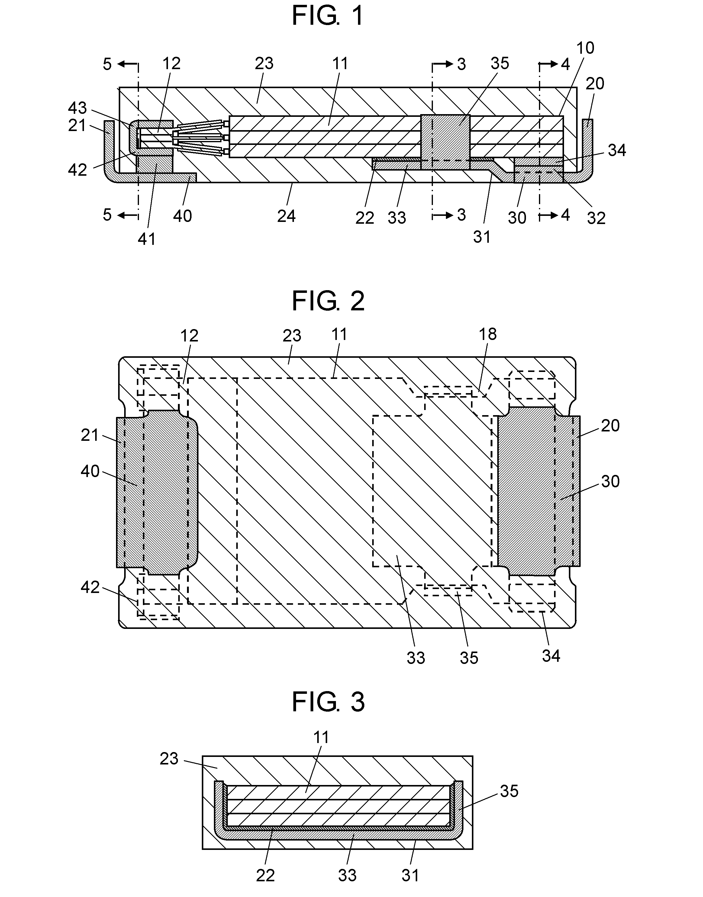
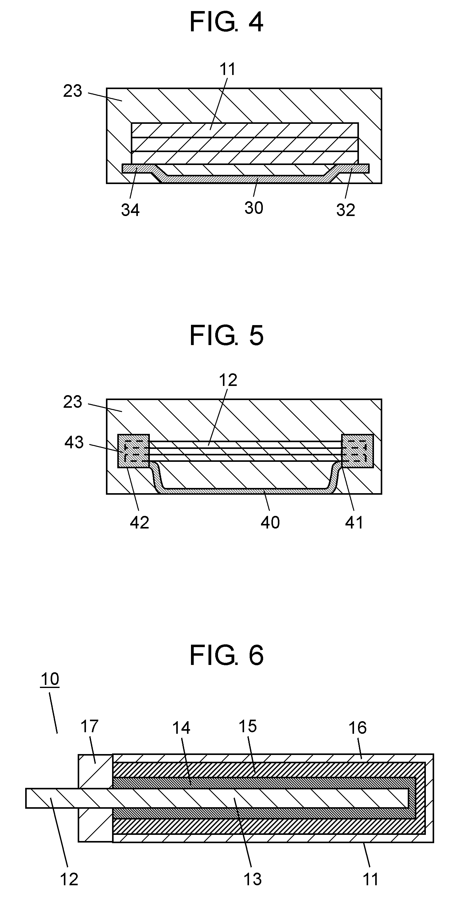
[0023]FIG. 1 is a front cross sectional view of a solid electrolytic capacitor according to this embodiment, and FIG. 2 is a bottom view of the same. FIG. 3 is a cross sectional view of a cathode connection portion taken along a line 3-3 illustrated in FIG. 1. FIG. 4 is a cross sectional view of a cathode support portion taken along a line 4-4 illustrated in FIG. 1. FIG. 5 is a cross sectional view of an anode connection portion taken along line 5-5 illustrated in FIG. 1. FIG. 6 is a cross sectional view of a capacitor element included in the solid electrolytic capacitor according to the embodiment.

[0024]As illustrated in FIG. 1, a solid electrolytic capacitor according to the embodiment includes a plurality of flat capacitor elements 10, cathode terminal 20, anode terminal 21, and enclosure resin 23. Capacitor element 10 includes cathode portion 11 and anode portion 12. Cathod...


PUM


Abstract

A solid electrolytic capacitor includes a capacitor element including a cathode portion and an anode portion, a cathode terminal bonded to the cathode portion, an anode terminal bonded to the anode portion, and an enclosure resin covering the capacitor element. The cathode terminal includes a cathode lower surface portion, a cathode connection portion, and a cathode support portion. The cathode connection portion is connected to an end portion of the cathode lower surface portion on an anode side and bonded to the cathode portion through a conductive adhesive. The cathode support portion is connected to a side portion of the cathode lower surface and brought into contact with a lower surface of the cathode portion on an end portion side of the cathode portion without involving the conductive adhesive therebetween.

Description

BACKGROUND[0001]1. Technical Field[0002]The present invention relates to a solid electrolytic capacitor formed by connecting an external lead terminal to a capacitor element.[0003]2. Description of the Related Art[0004]Along with miniaturization, thinning, and digitalization of electronic equipment, a demand for a thin solid electrolytic capacitor used therein having a large capacitance and a low ESR (Equivalent Series Resistance) grows.[0005]As illustrated in FIG. 7, a conventional solid electrolytic capacitor is formed of capacitor element 51, cathode terminal 52 connected to a cathode portion, anode terminal 53 connected to an anode portion, and enclosure resin 55. Enclosure resin 55 covers part of cathode terminal 52, part of anode terminal 53, and capacitor element 51.[0006]Cathode terminal 52 is bent in a step-like pattern from a lower surface of cathode electrode 52 which is exposed from mounting surface 56, and an upper end portion thus bent is bonded to a lower surface of t...

Claims


Application Information

Patent Timeline
IPC IPC(8): H01G9/15
CPCH01G9/028H01G9/10H01G9/012H01G9/0036H01G9/15H01G9/08
Inventor KAWAHITO, KAZUOIWAKIRI, TAKASHI
Owner PANASONIC CORP
Why Eureka
Try Eureka