Magnetic resonance imaging system and radiotherapy apparatus with an adjustable axis of rotation

a magnetic resonance imaging and rotational adjustment technology, applied in the field of magnetic resonance imaging system and radiotherapy apparatus with adjustable rotational adjustment, can solve the problems of limited useful magnet space and insufficient magnet space in the magnet field, and achieve the effect of guiding radiotherapy treatments using magnetic resonance imaging

Inactive Publication Date: 2013-08-29
KONINKLIJKE PHILIPS ELECTRONICS NV
View PDF6 Cites 11 Cited by
  • Summary
  • Abstract
  • Description
  • Claims
  • Application Information

AI Technical Summary

Benefits of technology

[0046]In another embodiment the mechanical actuator comprises a hydraulic system. The use of a hydraulic system may be beneficial because hydraulic systems can be used to lift very heavy objects. In addition for the hydraulic system can be located away from the magnetic resonance imaging system. This saves valuable space in the examination room and also the machinery used to lift or move the mechanical actuator is away from the magnetic resonance imaging system and therefore can be designed to function without concern to the high magnetic field generated by the magnetic resonance imaging magnet.

Problems solved by technology

A difficulty encountered in guiding radiotherapy treatments using magnetic resonance (MR) imaging is the limited space in magnets that are useful for clinical imaging, such as cylindrical superconducting magnets.
For such magnets there is simply is not sufficient space in a magnet to position the target zone relative to the rotational axis of the radiotherapy source.

Method used


Image

  • Magnetic resonance imaging system and radiotherapy apparatus with an adjustable axis of rotation
  • Magnetic resonance imaging system and radiotherapy apparatus with an adjustable axis of rotation
  • Magnetic resonance imaging system and radiotherapy apparatus with an adjustable axis of rotation

Examples


Embodiment Construction

[0060]Like numbered elements in these figures are either equivalent elements or perform the same function. Elements which have been discussed previously will not necessarily be discussed in later figures if the function is equivalent.

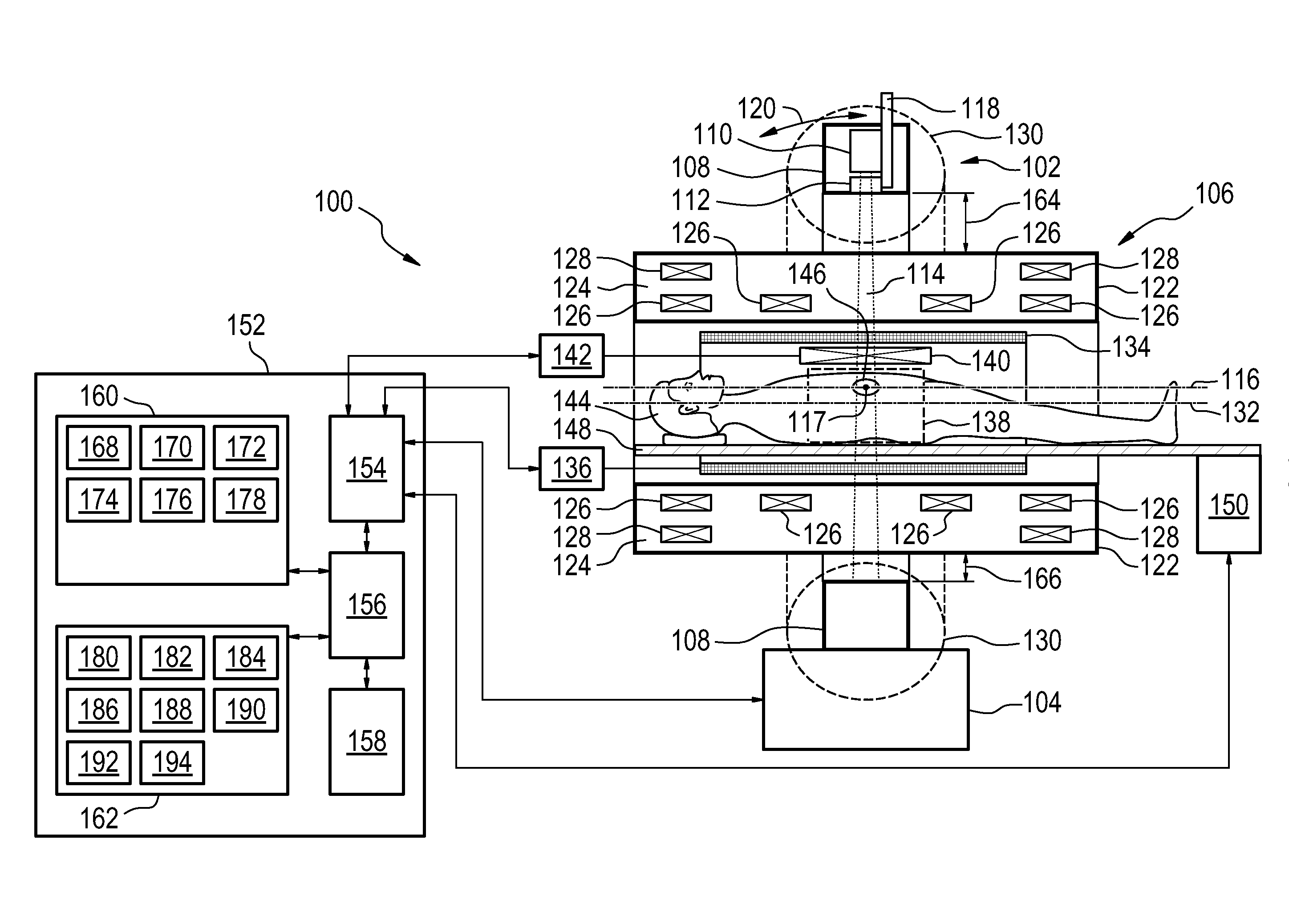
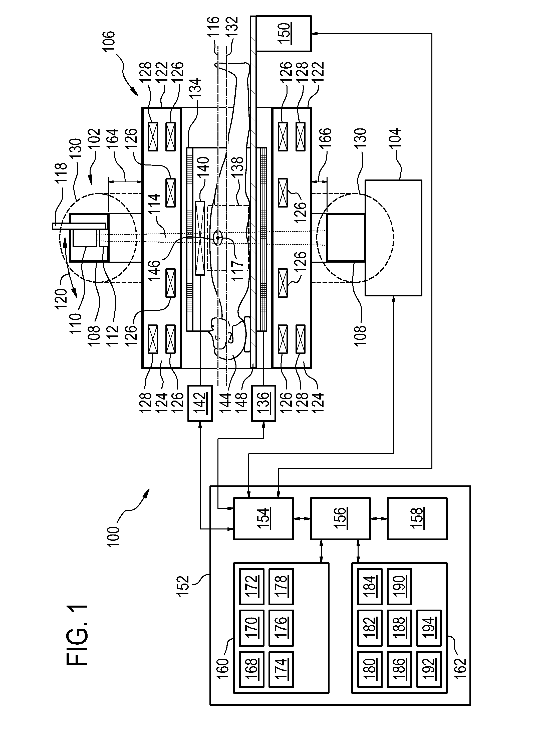
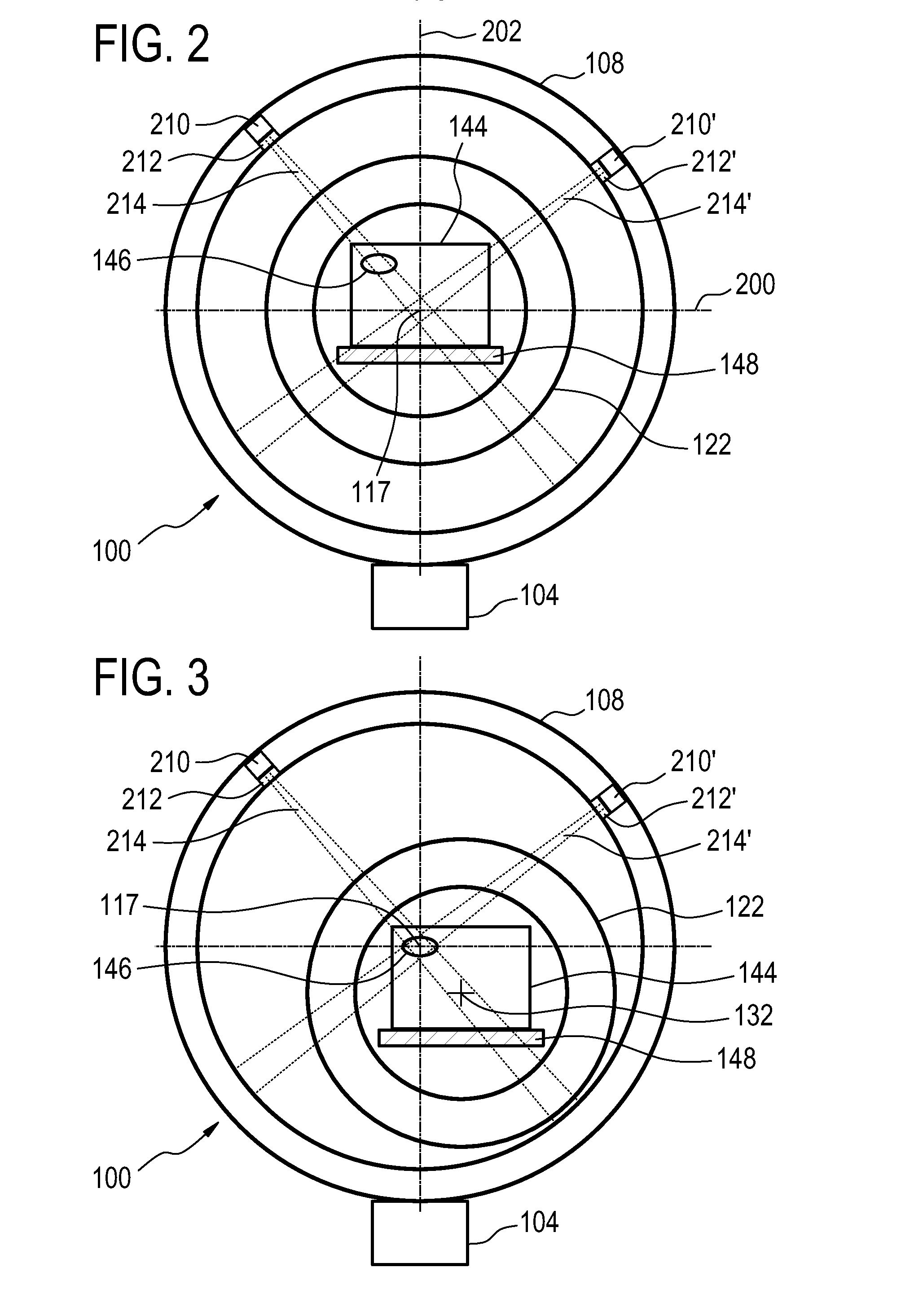
[0061]FIG. 1 shows a cross-sectional and functional view of a therapeutic apparatus 100 according to an embodiment of the invention. The therapeutic apparatus 100 is shown as comprising a radiotherapy apparatus 102, a mechanical actuator 104 and a magnetic resonance imaging system 106. The radiotherapy apparatus 102 comprises a ring mechanism 108. The ring mechanism 108 supports a radiotherapy source 110. The radiotherapy source 110 is representative and may be a LINAC x-ray source, an x-ray 2 and a radioisotope gamma radiation source. Adjacent to the radiotherapy source 110 is a beam collimator 112 for collimating a radiation beam 114 that is generated by the radiotherapy source 110. The ring mechanism 108 is also adapted for rotating the radiotherapy ...


PUM


Abstract

A therapeutic apparatus (100) comprising: a radio therapy apparatus (102) for treating a target zone (146) of a subject (144), wherein the radio therapy apparatus comprises a radio therapy source (110) for generating electromagnetic radiation (114), wherein the radio therapy apparatus is adapted for rotating the radio therapy source about a rotational point (116); a mechanical actuator (104) for supporting the radio therapy apparatus and for moving the position and/or orientation of the rotational point; and a magnetic resonance imaging system (106) for acquiring magnetic resonance data (170) from an imaging zone (138), wherein the target zone is within the imaging zone, wherein the magnetic resonance imaging system comprises a magnet (122) for generating a magnetic field within the imaging zone, wherein the radio therapy source is adapted for rotating at least partially about the magnet.

Description

TECHNICAL FIELD[0001]The invention relates to apparatuses for treating a target zone of a subject with radiotherapy, in particular the invention relates to radiotherapy apparatuses guided by magnetic resonance imaging.BACKGROUND OF THE INVENTION[0002]Integration of MR and Linear Accelerators (LINAC) opens new horizons in Radiotherapy by improved lesion targeting, especially for moving organs. In a practical implementation proposal, the LINAC rotates around the patient to hit the gross target volume (GTV) and clinical target volume (CTV) from multiple angles while minimizing the radiation exposure for surrounding tissues. In routine practice of Radiotherapy (RT), the patient is positioned relative to the stationary center of the rotating arc carrying the RT source. Positioning implies both height and lateral adjustment of the patient table. This positioning is required to optimize the dose in the lesion beyond variation that can be obtained by applying RT rays from different angles.[...

Claims


Application Information

Patent Timeline
Patent Type & Authority Applications(United States)
IPC IPC(8): A61N5/10A61B5/055
CPCA61N5/1049A61N2005/1055G01R33/4808A61N5/1081A61N5/1039A61N5/1048A61B5/055
Inventor VAN DEN BRINK, JOHAN SAMUEL
Owner KONINKLIJKE PHILIPS ELECTRONICS NV
Why Eureka
Try Eureka