Diagnostic method and diagnostic device for a vehicle component of a vehicle

a technology for diagnosing method and vehicle, which is applied in the direction of instruments, traffic control systems, structural/machine measurement, etc., can solve the problems of system failure, system failure, and inability to detect impending failure of important systems, so as to reduce the probability of vehicle components failing during vehicle operation or avoid the effect of failur

Inactive Publication Date: 2013-08-29
ROBERT BOSCH GMBH
View PDF8 Cites 124 Cited by
  • Summary
  • Abstract
  • Description
  • Claims
  • Application Information

AI Technical Summary

Benefits of technology

[0004]An object of the present invention is to provide a diagnostic method for a vehicle component of a vehicle, which overcomes the conventional disadvantages, and in which the probability of failure of the vehicle component during vehicle operation is reduced or avoided.
[0012]The recording of the operating parameters particularly has the effect that the status of the vehicle component is able to be recorded, or rather determined. Thus one may make a statement particularly in an advantageous manner on whether a functional restriction of the vehicle component exists or is foreseeable. Correspondingly, the status message may then particularly be formed that is sent to the server external to the vehicle, to evaluate this.
[0024]According to a further specific embodiment, it may be provided that a respective operating parameter be recorded by additional different vehicle components, whereby, as a function of the recorded operating parameters, in each case a status message corresponding to the respective status of the additional vehicle components is transmitted to a central diagnostic device that is internal to the vehicle, which, as a function of the transmitted status messages, sends the status message to the server external to the vehicle. This, then means in particular that the individual vehicle components transmit their respective status, that is, their status in the context of a plurality of vehicle components, also designated as substatus, to the central diagnostic device, which thereupon, in an advantageous manner, is then able to form a status corresponding to the overall status corresponding to the plurality of vehicle components, so that it is then able to be sent to the server external to the vehicle. Because of that, the receiver of the status message is able to receive an overview of the overall status of the vehicle with its individual systems including the plurality of vehicle components. An even more inclusive and more accurate error analysis is thus made possible in an advantageous manner. Such a diagnostic device may preferably be provided respectively in all vehicles.
[0026]In another specific embodiment it may be provided that a central diagnostic device is provided which is connected to the recording device using a bus. Such a bus may be a field bus, for example. In particular, such a bus is a CAN bus. In this instance, the formulation “CAN” stands for “controller area network”. This, then means in particular that using the bus advantageously makes possible the networking of the control units of the vehicle components.
[0037]According to still another specific embodiment, it may be provided that a data packet including a recorded operating parameter and the status message is formed. This data packet may then be advantageously sent to the server external to the vehicle, so that it is able to evaluate the data packet appropriately. Thereby, in an advantageous manner, both the status message and the recorded operating parameter may efficiently be sent to the server external to the vehicle in one sending process.

Problems solved by technology

An impending failure of vehicle systems of a motor vehicle is generally not systematically detected.
This is why an impending failure of an important system is frequently not able to be detected early enough.
These systems may therefore fail, for instance, during the operation of the vehicle.

Method used


Image

  • Diagnostic method and diagnostic device for a vehicle component of a vehicle
  • Diagnostic method and diagnostic device for a vehicle component of a vehicle
  • Diagnostic method and diagnostic device for a vehicle component of a vehicle

Examples


Embodiment Construction

[0044]In the following text, the same reference numerals are used for the same features.

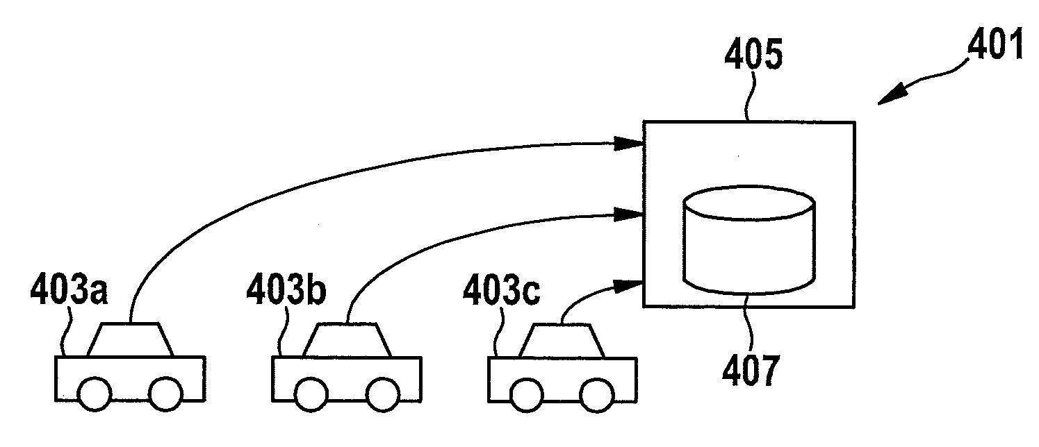
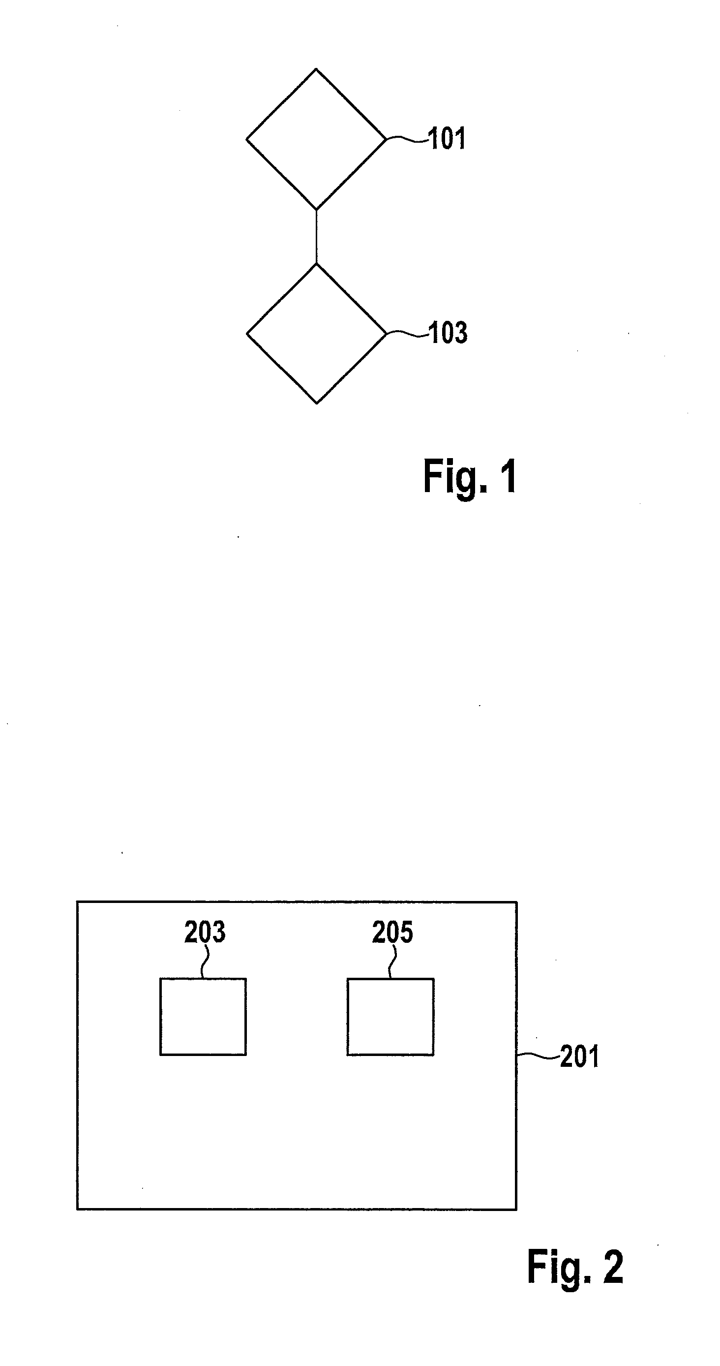
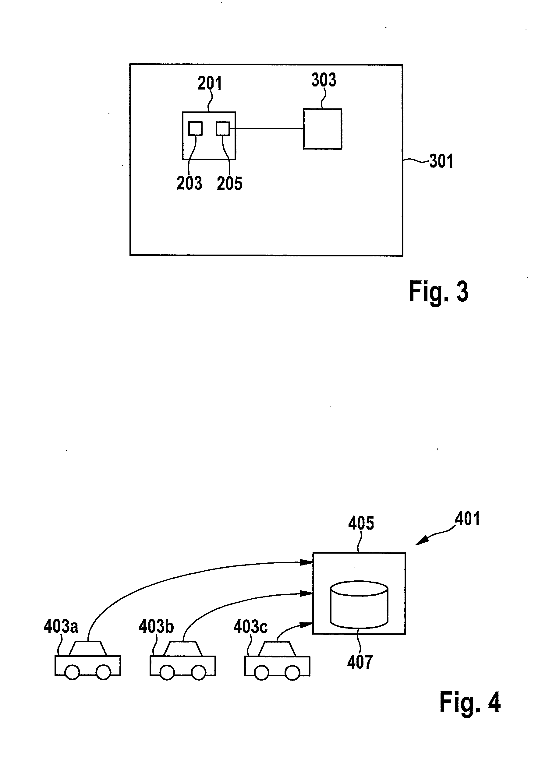
[0045]FIG. 1 shows a flow chart of a diagnostic method for a vehicle component of a vehicle. In this instance, a plurality of vehicles are provided each with the same vehicle component. According to a step 101, an operating parameter of the respective vehicle component is recorded during the operation of the vehicle. During a step 103, as a function of the recorded operating parameter, a status message corresponding to a status of the respective vehicle component is sent to a server outside the vehicle for an evaluation of the status message.

[0046]FIG. 2 shows a diagnostic device 201 for a vehicle component (not shown) of a vehicle (not shown).

[0047]Diagnostic device 201 includes a recording device 203 for recording an operating parameter of the vehicle component. In addition, diagnostic device 201 includes a sending device 205 for sending a status message corresponding to a status of the vehicle...


PUM


Abstract

A diagnostic method for a vehicle component of a vehicle, a plurality of vehicles each having the same vehicle component being provided; during the operation of the vehicles, an operating parameter of the respective vehicle component being recorded and, as a function of the recorded operating parameter, a status message corresponding to the status of the respective vehicle component being sent to a server for an evaluation of the status message. A corresponding diagnostic device, a corresponding diagnostic system and a computer program are also described.

Description

CROSS REFERENCE[0001]The present application claims the benefit under 35 U.S.C. §119 of German Patent Application No. DE 102012202914.1 filed on Feb. 27, 2012, which is expressly incorporated herein by reference in its entirety.FIELD[0002]The present invention relates to a diagnostic method and a diagnostic device for a vehicle component of a vehicle. Furthermore, the present invention relates to a diagnostic system for a vehicle component of a vehicle and a computer program.BACKGROUND INFORMATION[0003]An impending failure of vehicle systems of a motor vehicle is generally not systematically detected. Some systems are tested at greater intervals at repair station inspections, and other systems are not tested at all. This is why an impending failure of an important system is frequently not able to be detected early enough. These systems may therefore fail, for instance, during the operation of the vehicle.SUMMARY[0004]An object of the present invention is to provide a diagnostic meth...

Claims


Application Information

Patent Timeline
Patent Type & Authority Applications(United States)
IPC IPC(8): G06F17/00
CPCG08G1/0112G08G1/20G06F17/00G07C5/0808G07C5/085G07C5/008
Inventor NORDBRUCH, STEFANKNOOP, MICHAEL
Owner ROBERT BOSCH GMBH
Why Eureka
Try Eureka