Using two thermal switches to control a hybrid lamp

a hybrid lamp and thermal switch technology, applied in the field of lamps, can solve the problems of not always providing not providing an efficient and effective manner for determining when to shut off the incandescent lamp, and unable to provide an accurate assessment of the actual thermal conditions of the discharge vessel. to achieve the effect of accurately determining the time to shut o

Inactive Publication Date: 2013-09-05
GENERAL ELECTRIC CO
View PDF2 Cites 3 Cited by
  • Summary
  • Abstract
  • Description
  • Claims
  • Application Information

AI Technical Summary

Benefits of technology

[0008]A lamp assembly of the present disclosure provides for instant light, and is also an energy saving lamp that advantageously uses two light sources in a single outer bulb that more accurately determines when to shut off the secondary, instant light source.
[0010]The preferred lamp assembly includes a lamp base having a compartment. A first or fluorescent light or lamp source (efficient, long warm-up) and a second or incandescent light or lamp source (instantaneous light output, less efficient) are each mounted to the lamp base. An envelope of the lamp assembly forms a cavity around at least the fluorescent and incandescent lamp sources. A power control module preferably received in a lamp base compartment is operatively connected to the lamp sources. The thermal sensor members monitor a temperature of the lamp assembly at two different locations so that a more accurate determination regarding whether to terminate power supplied to the incandescent lamp source can be made.
[0016]A primary benefit of the present disclosure is the ability to provide instant light in an energy saving lamp assembly.
[0018]Still another benefit is associated with monitoring the temperature in order to assure that a preselected percentage of full light output has been reached before shutting off the secondary lamp source.

Problems solved by technology

Although it has been suggested to simultaneously turn on both lamps in order to result in instant light from the incandescent lamp, and then subsequently terminate or switch off the incandescent lamp to obtain the benefits of the energy efficient CFL, these known arrangements do not provide an efficient and effective manner for determining when to shut off the incandescent lamp, i.e., using the compact fluorescent lamp exclusively once the CFL has warmed up.
Therefore, when to switch off the secondary incandescent lamp source presents a challenge.
Unfortunately, this solution does not always provide an accurate assessment of the actual thermal conditions of the discharge vessel.
Further, locating a thermally sensitive element in a lamp assembly is potentially impacted by temperature variations caused by different positions of the lamp e.g. vertically upright, horizontal, or inverted.
Likewise, other indirect factors can impact and are potentially inaccurate in defining when the light output of the primary light source (CFL) has stabilized.
As a result, the use of a single thermally sensitive element does not provide an accurate representation of the heat conditions nor does the thermal sensor necessarily provide an accurate indicator of when to terminate operation of the secondary or incandescent lamp source.
Again, this solution is not sufficiently accurate since various conditions may suggest a different time period, either shorter or longer.

Method used


Image

  • Using two thermal switches to control a hybrid lamp
  • Using two thermal switches to control a hybrid lamp
  • Using two thermal switches to control a hybrid lamp

Examples


Embodiment Construction

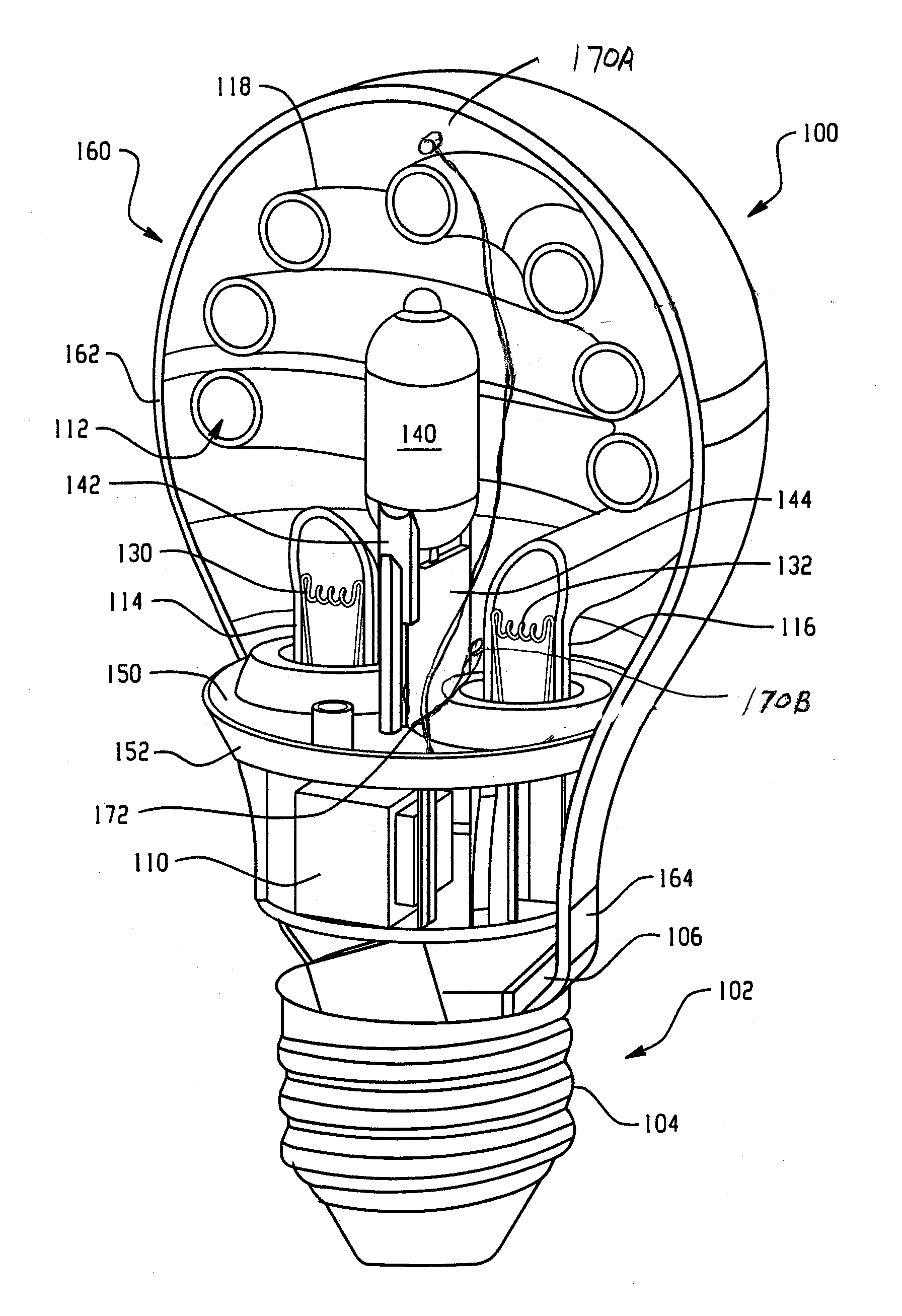
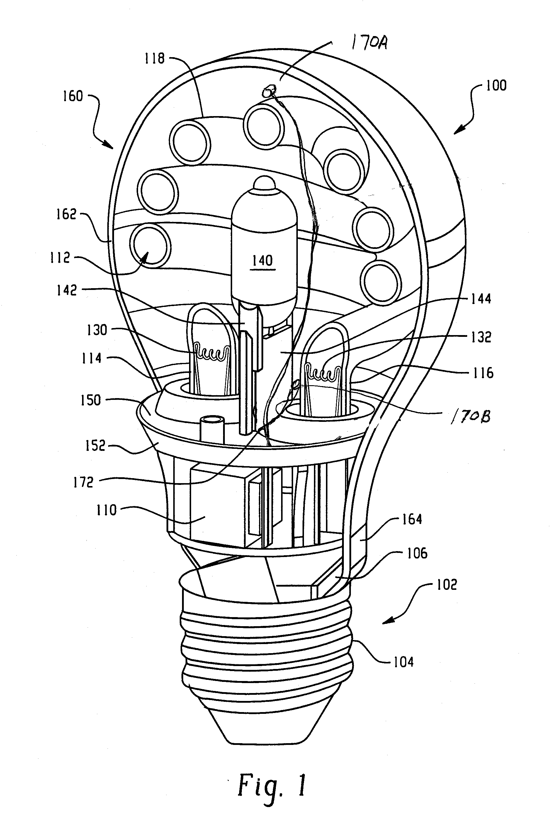
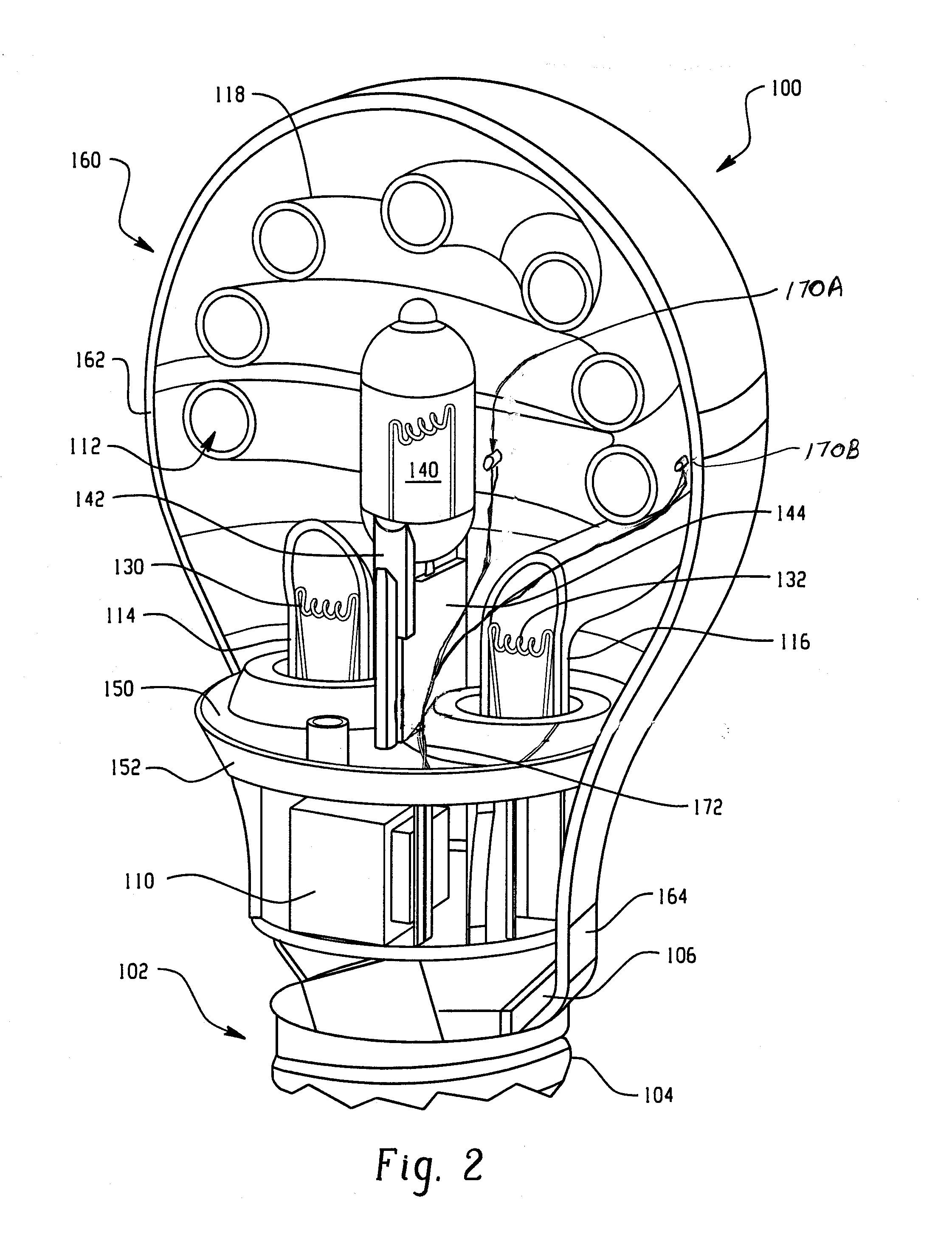
[0022]FIGS. 1 and 2 show a lamp assembly 100, and more particularly a combination of a discharge or preferably a fluorescent lamp source such as compact fluorescent lamp (CFL) assembly (that is generally referred to herein as an energy saving lamp or light source) and a secondary light source such as an incandescent lamp assembly that advantageously provides instant light. A lamp base 102 includes a mechanical and electrical arrangement for receipt in an associated lamp socket (not shown) to mechanically support the lamp assembly 100 and provide power to operate the lamp assembly. More particularly, and without need to be limiting, a conventional Edison-base 102 is shown that includes a conductive, threaded metal shell 104 for threaded receipt in an associated lamp socket, and typically includes an electrical eyelet or second contact (not shown) spaced from the threaded shell 104 by insulating material at the lower end of the lamp assembly. This arrangement provides a two lead arran...


PUM


Abstract

A lamp assembly provides both instant light through use of an incandescent / halogen light / lamp source and an energy saving type light provided by a compact fluorescent light / lamp source. Both light sources are enclosed within a common envelope or outer bulb. First and second thermal sensors are provided in the lamp envelope at spaced locations to monitor the temperature of the lamp. When the sum of these two temperatures reaches a preselected value, power to the incandescent lamp source is terminated. Alternatively, when the difference these two temperatures reaches a preselected value, power to the incandescent lamp source is terminated.

Description

BACKGROUND OF THE DISCLOSURE[0001]This disclosure is directed to a lamp assembly, such as a lamp assembly that provides energy savings and also provides for instant light.[0002]One proposed solution to reducing the time to full light while still obtaining the benefits of an energy savings lamp is to combine two lamps in one unit, sometimes referred to as a hybrid lamp. More particularly, a compact fluorescent lamp (CFL) and a conventional incandescent lamp are combined. Although it has been suggested to simultaneously turn on both lamps in order to result in instant light from the incandescent lamp, and then subsequently terminate or switch off the incandescent lamp to obtain the benefits of the energy efficient CFL, these known arrangements do not provide an efficient and effective manner for determining when to shut off the incandescent lamp, i.e., using the compact fluorescent lamp exclusively once the CFL has warmed up.[0003]Before preheating is complete, there is no light emiss...

Claims


Application Information

Patent Timeline
Patent Type & Authority Applications(United States)
IPC IPC(8): H05B35/00F21Y113/20
CPCH05B41/46H05B41/232H01J61/523H05B35/00H05B41/295
Inventor LUCZ, PETERBANKUTI, LASZLOLONG, QISUN, DEVIN
Owner GENERAL ELECTRIC CO
Why Eureka
Try Eureka