Image capturing unit, color measuring device, image forming device, color measuring system, and color measuring method

a color measuring device and image forming technology, applied in the field of image capture units, can solve the problems of fluctuation in color reproducibility, large number high cost of spectrophotometric color measuring devices,

Active Publication Date: 2013-09-05
RICOH KK
View PDF4 Cites 31 Cited by
  • Summary
  • Abstract
  • Description
  • Claims
  • Application Information

AI Technical Summary

Problems solved by technology

However, the amount of color material, for example, the discharging amount of ink in the ink injection image forming device fluctuates according to the state of the nozzle of the head, viscosity fluctuation of the ink, fluctuation of the discharge drive element (piezo element, etc.), and hence causes fluctuation in color reproducibility.
However, the spectrophotometric color measuring device is an expensive device mounted with a great number of sensors, and thus highly accurate color measurement is desired to be carried out using a less expensive device.
H5-223642, the position relationship between the subject, the reference color chart, and the color video camera is difficult to maintain constant, and the image capturing conditions change for every imaging and stable imaging may not be carried out.

Method used


Image

  • Image capturing unit, color measuring device, image forming device, color measuring system, and color measuring method
  • Image capturing unit, color measuring device, image forming device, color measuring system, and color measuring method
  • Image capturing unit, color measuring device, image forming device, color measuring system, and color measuring method

Examples


first embodiment

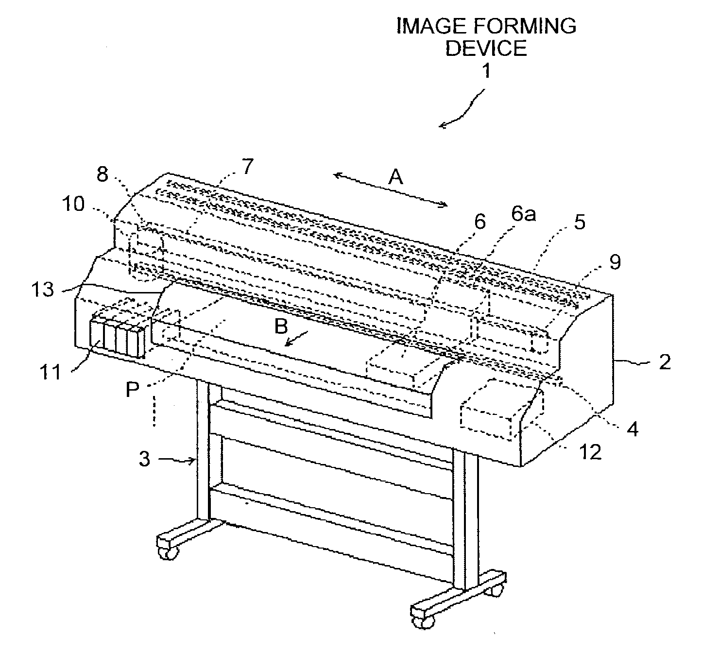
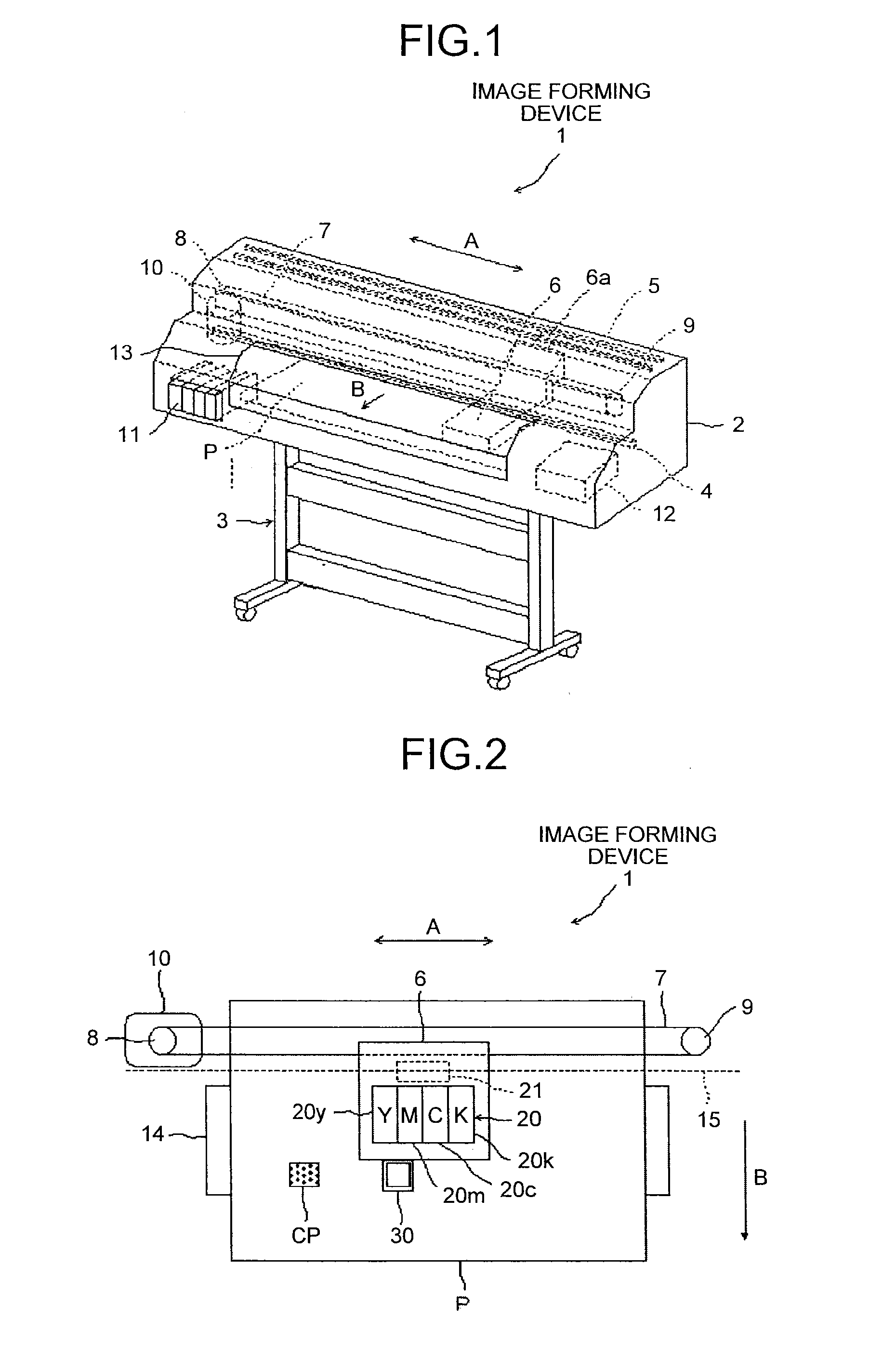
[0054]FIG. 1 to FIG. 28 are views illustrating a first embodiment of an image capturing unit, a color measuring device, an image forming device, a color measuring system, and a color measuring method of the present invention, where FIG. 1 is a schematic perspective view of an image forming device 1 applied with the first embodiment of the image capturing unit, the color measuring device, the image forming device, the color measuring system, and the color measuring method of the present invention.

[0055]In FIG. 1, the image forming device 1 has a main body housing 2 arranged on a main body frame 3. A main guide rod 4 and a sub-guide rod 5 are arranged across in a main-scanning direction illustrated with a double headed arrow A in FIG. 1 in the main body housing 2. The main guide rod 4 movably supports a carriage 6. The carriage 6 includes a coupling piece 6a that engages with the sub-guide rod 5 to stabilize the position of the carriage 6.

[0056]The image forming device 1 has a timing ...

second embodiment

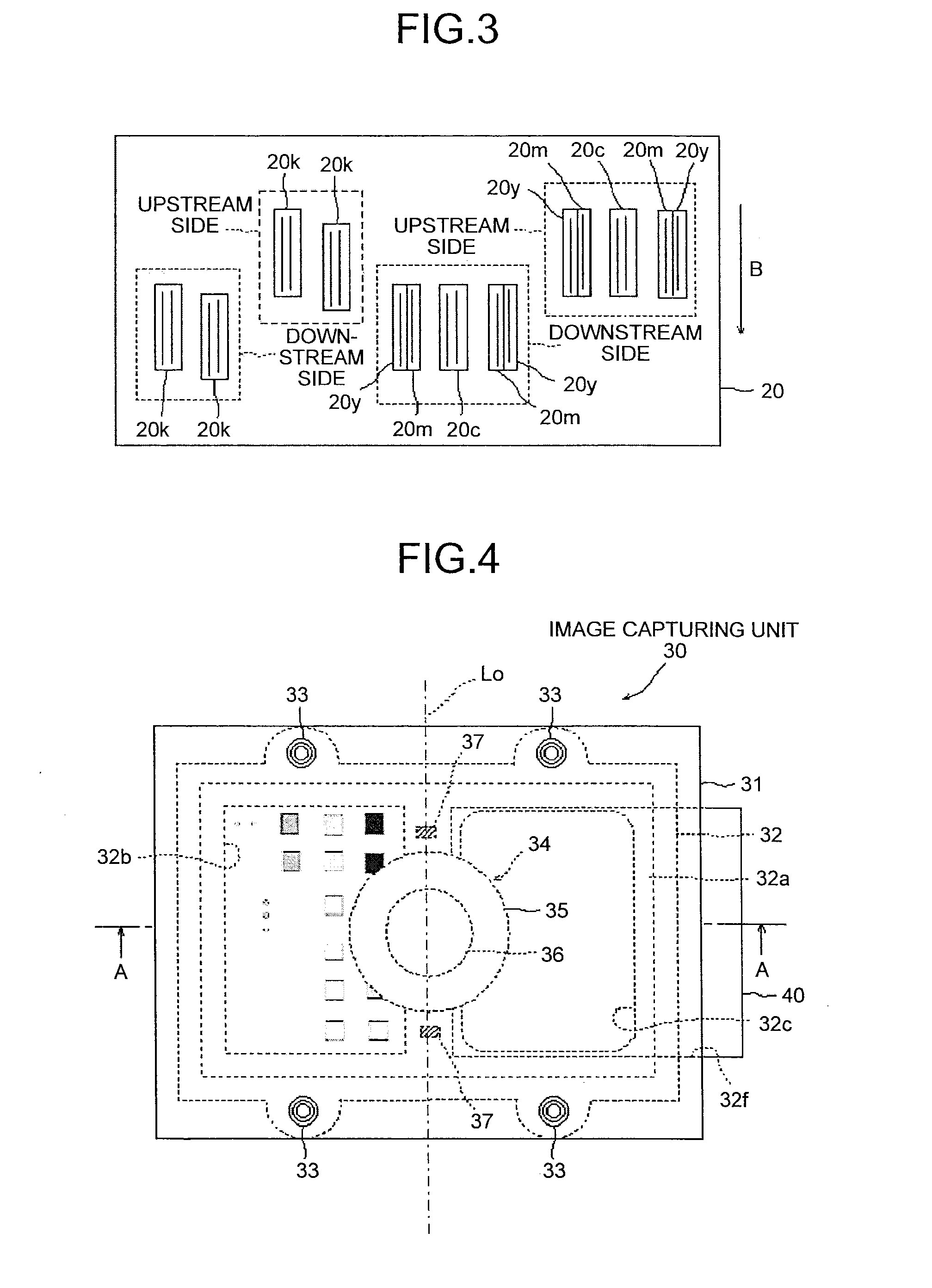
[0175]FIG. 29 to FIG. 34 are views illustrating a second embodiment of the image capturing unit, the color measuring device, the image forming device, the color measuring system, and the color measuring method of the present invention. FIG. 29 is a plan view of an image capturing unit 300 mounted on an image forming device applied with the second embodiment of the image capturing unit, the color measuring device, the image forming device, the color measuring system, and the color measuring method of the present invention. FIG. 30 is a cross-sectional view taken in the direction of arrow A-A of FIG. 29. The present embodiment is applied to the image forming device similar to the image forming device of the first embodiment. Furthermore, application is made to the image capturing unit 300 similar to the image capturing unit 30 illustrated in FIG. 4 and FIG. 8. In the description of the present embodiment, the same reference numerals are denoted on the configuring portions similar to t...


PUM


Abstract

An image capturing unit includes a sensor section that images a predetermined range including a subject; a reference chart section that is imaged by the sensor section with the subject; and an illumination light source that illuminates the subject and the reference chart section. The illumination light source is arranged at a position where a mirror reflection region that mirror reflects light entering from the illumination light source to the sensor section is outside a region of the subject and the reference chart section.

Description

CROSS-REFERENCE TO RELATED APPLICATIONS[0001]The present application claims priority to and incorporates by reference the entire contents of Japanese Patent Application No. 2012-45960 filed in Japan on Mar. 1, 2012, Japanese Patent Application No. 2012-73981 filed in Japan on Mar. 28, 2012 and Japanese Patent Application No. 2013-030374 filed in Japan on Feb. 19, 2013.BACKGROUND OF THE INVENTION[0002]1. Field of the Invention[0003]The present invention relates to an image capturing unit, a color measuring device, an image forming device, a color measuring system and a color measuring method.[0004]2. Description of the Related Art[0005]An image forming device such as a color ink injection image forming device, a color electrophotography image forming device, and the like is used in offset printing of advertising media, pamphlets, and the like in which the number of print copies are relatively few but in which high quality image is demanded with improvement in image quality.[0006]In t...

Claims


Application Information

Patent Timeline
Patent Type & Authority Applications(United States)
IPC IPC(8): H04N1/60
CPCH04N1/6033H04N1/00045H04N1/0087H04N1/0009H04N1/0282H04N1/00087G06K15/102H04N1/50H04N1/00023H04N1/034G06K2215/0094G06K2215/101G06K15/14
Inventor YOKOZAWA, SUGURUSATOH, NOBUYUKISUZUKI, YASUYUKIKOBAYASHI, MASATOSAKURADA, YUICHIYORIMOTO, MAMORUOKADA, TATSUHIKOHORIKAWA, DAISAKUSHIGEMOTO, MASAHIROTAKEI, KAZUSHISUZUKI, HIDEAKIIWANAMI, SATOSHI
Owner RICOH KK
Why Eureka
Try Eureka