X-ray imaging apparatus
a technology of x-ray imaging and holding fixtures, which is applied in the direction of instruments, patient positioning for diagnostics, radiation generation arrangements, etc., can solve the problems of poor portability, time and effort required to assemble and install holding fixtures, and difficult to perform radiography quickly
- Summary
- Abstract
- Description
- Claims
- Application Information
AI Technical Summary
Benefits of technology
Problems solved by technology
Method used
Image
Examples
first embodiment
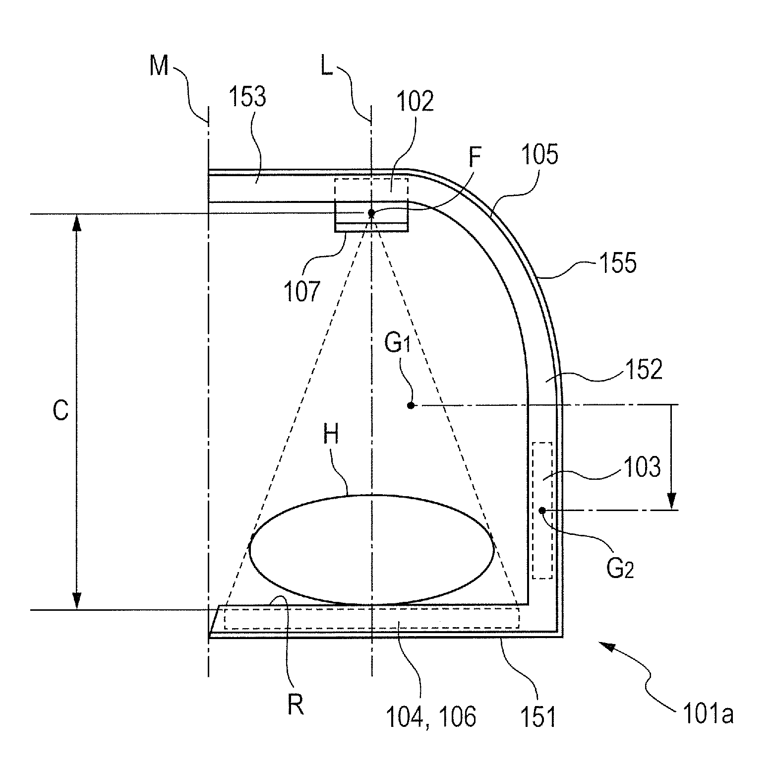
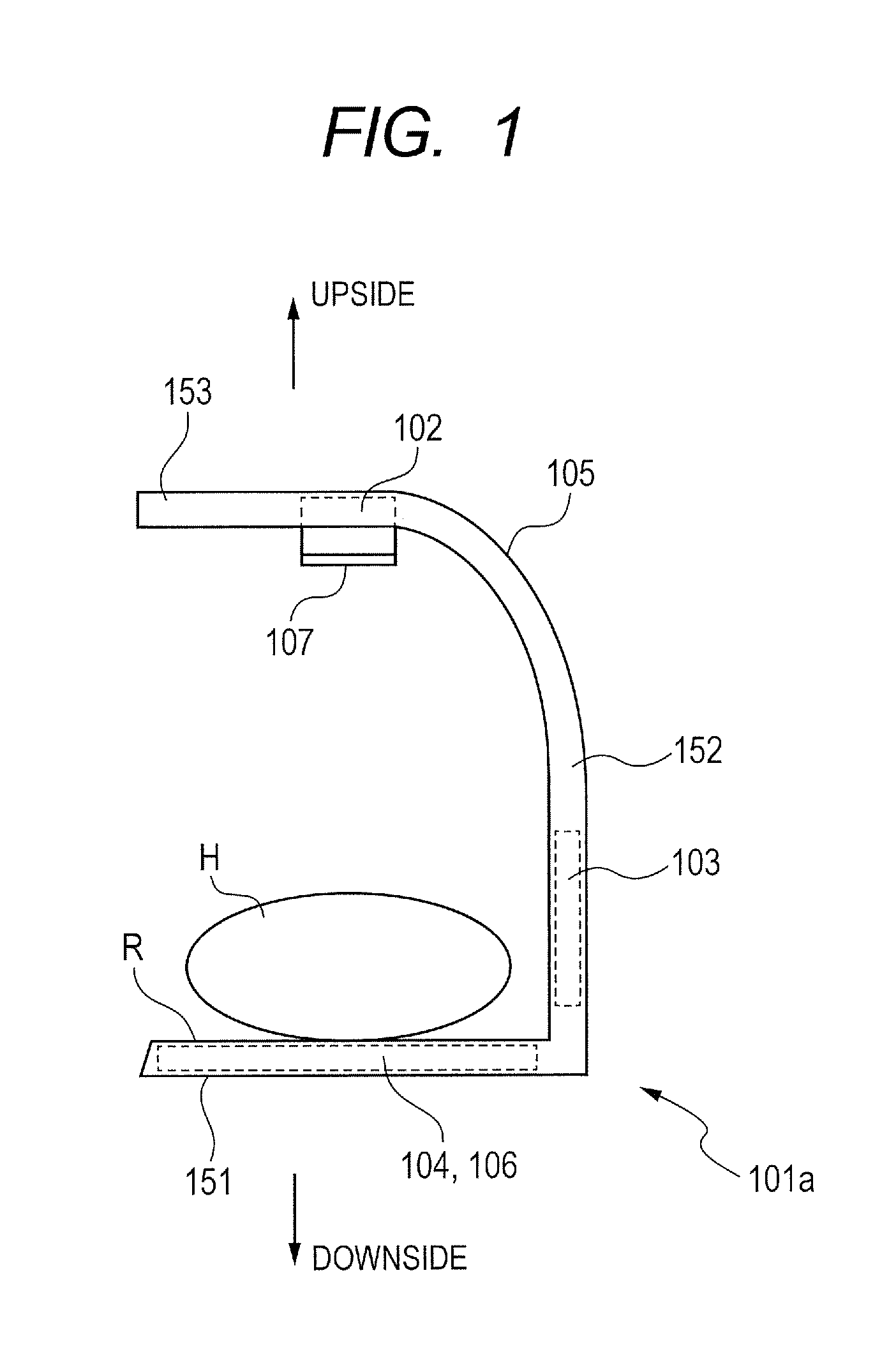
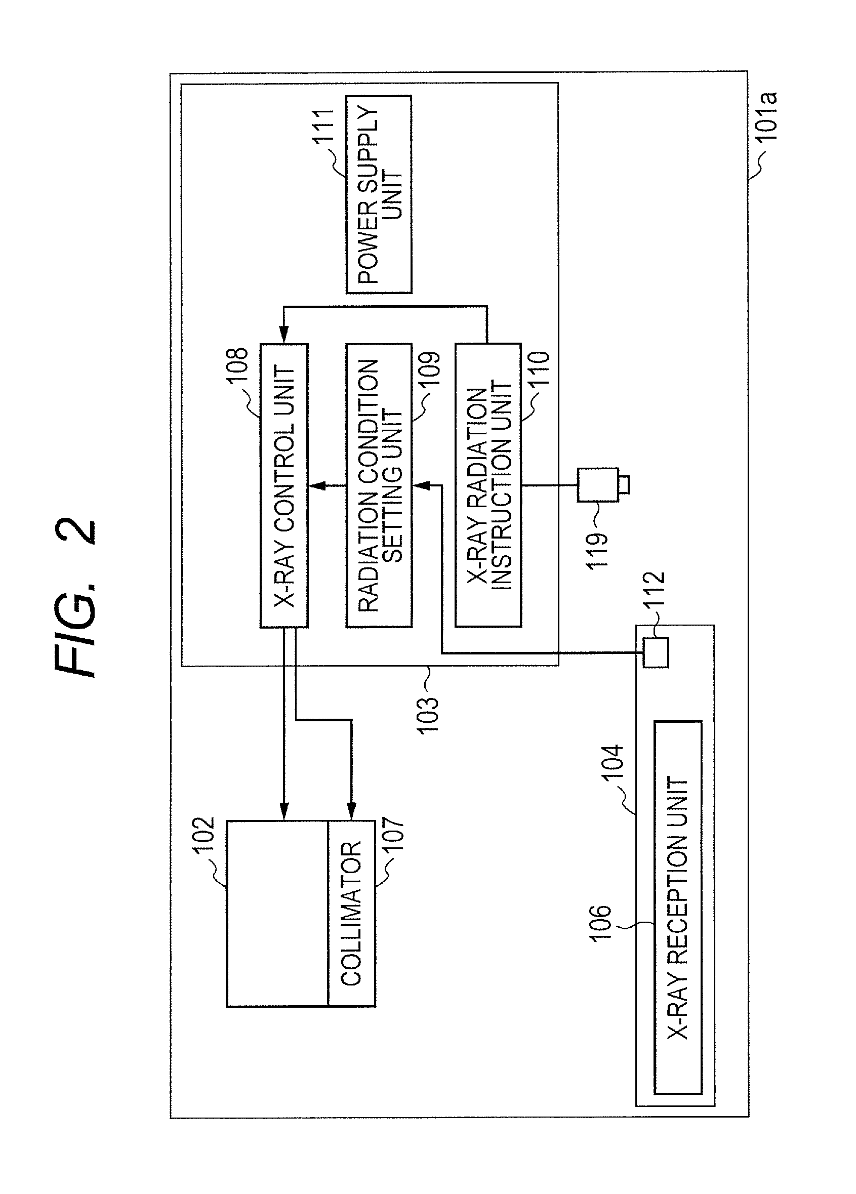
[0019]FIG. 1 schematically illustrates a structure of a main part of an X-ray imaging apparatus 101a according to a first embodiment of the present invention. FIG. 2 is a block diagram illustrating a system configuration of the main part of the X-ray imaging apparatus 101a according to the first embodiment of the present invention.
[0020]As illustrated in FIGS. 1 and 2, the X-ray imaging apparatus 101a according to the first embodiment includes an X-ray generation unit 102, a control unit 103, a storing unit 104, and an arm unit 105. Further, the X-ray generation unit 102, the control unit 103, and the storing unit 104 are fixed to the arm unit 105.
[0021]When the X-ray generation unit 102 receives an X-ray generation signal (described later) from an X-ray control unit 108 of the control unit 103, which is to be described later, the X-ray generation unit 102 generates an X-ray to irradiate a subject H with the X-ray. The X-ray generation unit 102 includes an X-ray tube (not shown) for...
second embodiment
[0069]Next, an X-ray imaging apparatus 101b according to a second embodiment of the present invention is described with reference to FIG. 7. Note that, the same reference numerals or symbols are assigned to the same components as those in the first embodiment, and hence redundant description is omitted. FIG. 7 is a block diagram schematically illustrating a system configuration of the X-ray imaging apparatus 101b according to the second embodiment. The X-ray imaging apparatus 101b according to the second embodiment includes an FPD sensor as the X-ray reception unit 106, and is connected to an HIS / RIS server (not shown) or a PACS server (not shown) so as to transmit / receive signals from / to the server(s).
[0070]As illustrated in FIG. 7, the X-ray imaging apparatus 101b according to the second embodiment includes the X-ray generation unit 102, the control unit 103, the storing unit 104, a sensor control unit 113, and a sensor information display unit 114. Further, the X-ray imaging appa...
third embodiment
[0086]Next, an X-ray imaging apparatus 101c according to a third embodiment of the present invention is described with reference to FIG. 9. FIG. 9 is a block diagram schematically illustrating a structure of a main part of the X-ray imaging apparatus 101c according to the third embodiment of the present invention. Note that, the same reference numerals or symbols are assigned to the same components as those in the first embodiment and the second embodiment, and hence redundant description is omitted.
[0087]As illustrated in FIG. 9, the X-ray imaging apparatus 101c according to the third embodiment is different from the X-ray imaging apparatus 101b according to the second embodiment in that the sensor control unit 113 is disposed in the control unit 103. Except for this, the structure is the same as that of the X-ray imaging apparatus 101b according to the second embodiment.
[0088]The sensor control unit 113 is disposed in the control unit 103 and is controlled by the control unit 103....
PUM
 Abstract
Description
Claims
Application Information
 - R&D
- Intellectual Property
- Life Sciences
- Materials
- Tech Scout
- Unparalleled Data Quality
- Higher Quality Content
- 60% Fewer Hallucinations
Browse by: Latest US Patents, China's latest patents, Technical Efficacy Thesaurus, Application Domain, Technology Topic, Popular Technical Reports.
© 2025 PatSnap. All rights reserved.Legal|Privacy policy|Modern Slavery Act Transparency Statement|Sitemap|About US| Contact US: help@patsnap.com


