Bicycle bottom bracket

Active Publication Date: 2013-09-05
PRAXIS WORKS
View PDF3 Cites 11 Cited by
  • Summary
  • Abstract
  • Description
  • Claims
  • Application Information

AI Technical Summary

Benefits of technology

[0014]According to aspects of the present teachings, in various embodiments one or more alignment washers may be disposed between one or both of the bearing cups and the bottom bracket shell, to compensate for imperfections of the shell faces on either side of the frame and to facilitate more accurate alignment of the cups with each other and/or with the central axis of the bottom bracket shell.
[0015]In other embodiments, the bearing cups may b

Problems solved by technology

A small diameter spindle is generally undesirable because it is not as stiff or strong as a larger spindle, thus increasing the amount of rider energy lost to flexure of the spindle.
Furthermore, to compensate for having a small diameter, loose bearing and cartridge style bottom bracket spindles are typically constructed from a relatively dense material such as steel or a steel alloy, which increases the weight of the bicycle.
On the other hand, if a larger diameter spindle is used with these designs, then relatively small bearings must be used, resulting in a significant decrease in durability.
However, because external bearing systems typically rely on the precise alignment of threaded bearing cups separately installed in opposite sides of the bottom bracket shell of the bicycle frame, these systems may suffer from the problems of improper bearing alignment and resulting fast bearing wear.
However, parallel and concentric alignment of the bearings on either side of the shell may be difficult to achieve in direct fit designs, because the alignment of the bearing axes relies on the precise machining of the bo

Method used


Image

  • Bicycle bottom bracket
  • Bicycle bottom bracket
  • Bicycle bottom bracket

Examples


Example

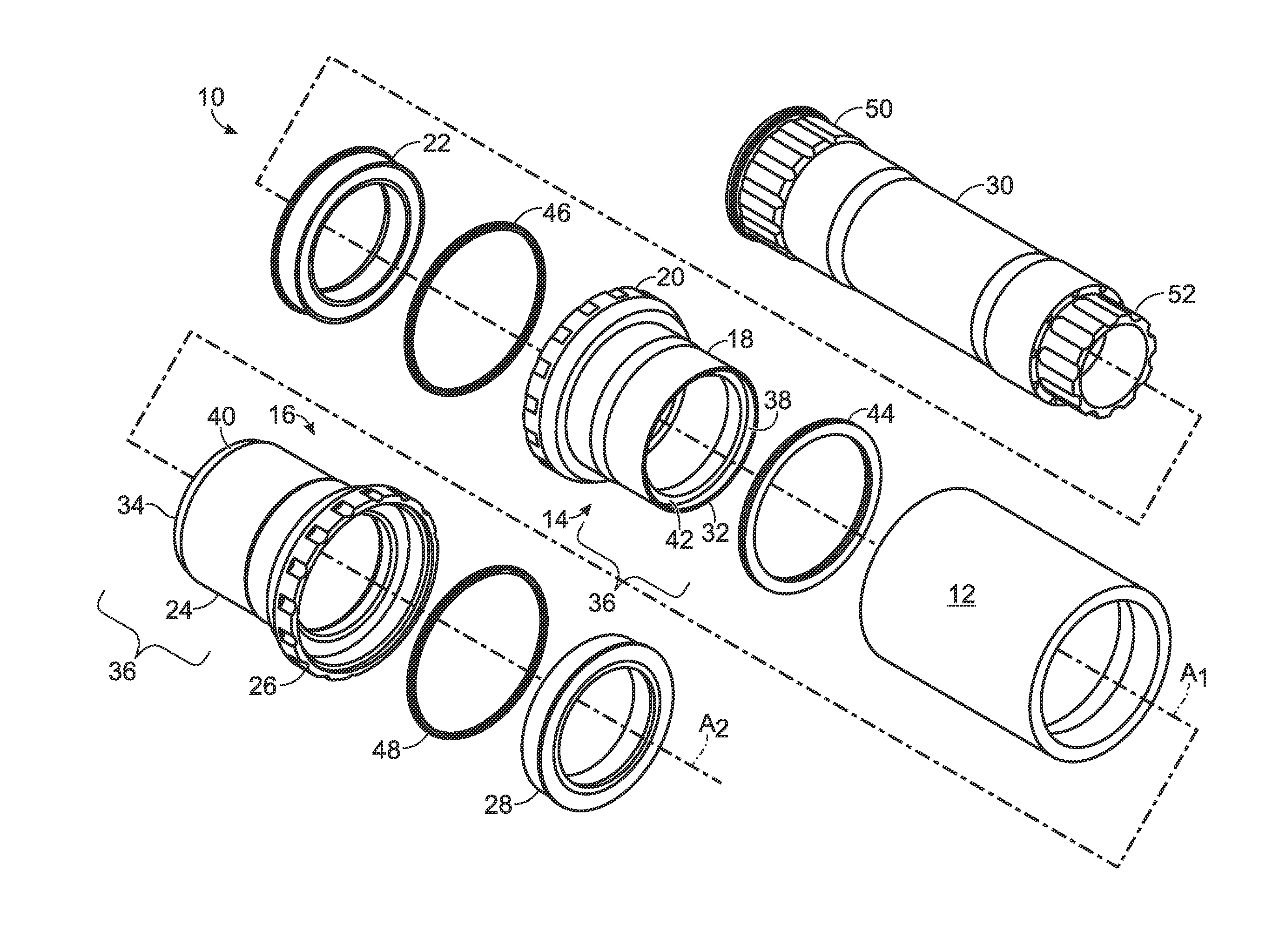
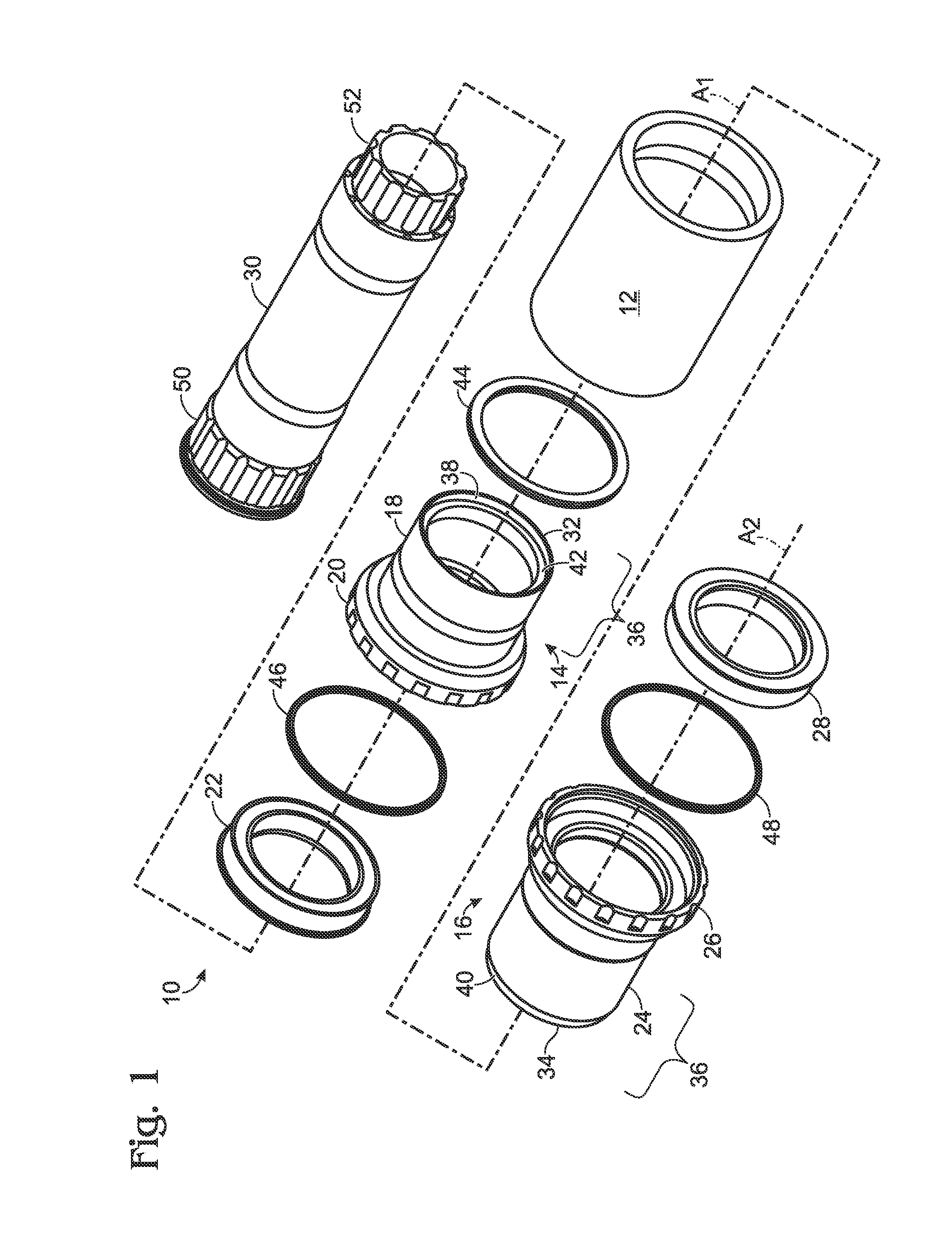
[0031]FIG. 1 depicts a first embodiment of a bicycle bottom bracket system, generally indicated at 10. Bottom bracket system 10 includes a bottom bracket shell 12, a left bearing cup generally indicated at 14, and a right bearing cup generally indicated at 16. Shell 12 may be an integrated bottom bracket shell portion of a bicycle frame, or it may be a separate shell which is configured to fit securely within the bottom bracket shell of the bicycle frame, for example by slip fitting, press fitting or the like. For simplicity, shell 12 will be described from this point forward as being an integrated portion of a bicycle frame. However, the other described components of the bottom bracket can also function with an appropriate choice of a separate shell that fits within a bicycle frame.

[0032]Left bearing cup 14 defines a left bearing rotation axis A1, which is the axis passing through the center of the left bearing cup and oriented perpendicular to its end faces. The left bearing cup i...


PUM


Abstract

An improved bicycle bottom bracket system and methods of manufacturing and installing such a system. The improved system may include bearings mounted within bearing cups on either side of the bottom bracket shell of a bicycle frame. The bearing cups may be threaded together, and one bearing cup may include a collet portion expandable by the other bearing cup.

Description

CROSS-REFERENCE TO RELATED APPLICATIONS[0001]This application is based upon and claims the benefit under 35 U.S.C. §119(e) of U.S. Provisional Patent Application Ser. No. 61 / 156,209, filed Feb. 27, 2009, U.S. Provisional Patent Application Ser. No. 61 / 244,910, filed Sep. 23, 2009, and is itself a continuation-in-part patent application to U.S. patent application Ser. No. 12 / 715,152, filed Mar. 1, 2010, all of which are incorporated herein by reference in their entirety for all purposes.INTRODUCTION[0002]The pedals of a bicycle are generally attached to crankarms on opposite sides of the bicycle frame. The crankarms are typically joined together by a spindle that passes through the frame, rigidly attaching the crankarms at positions that are rotated by 180 degrees relative to each other. This allows the alternating pedaling motion with which all bicycle riders are familiar. Accordingly, bicycles require a bearing assembly to allow for the rotation of the spindle and attached crankarm...

Claims


Application Information

Patent Timeline
IPC IPC(8): B60B27/00
CPCB62M3/003B60B27/0005Y10T29/49696B62K19/34B60B27/0078
Inventor EARLE, DAVID M.CHUANG, CHIN T.
Owner PRAXIS WORKS
Why Eureka
Try Eureka