Combination torsion spring, and shift mechanism provided with same
- Summary
- Abstract
- Description
- Claims
- Application Information
AI Technical Summary
Benefits of technology
Problems solved by technology
Method used
Image

Examples
Embodiment Construction
[0066]With reference now to the accompanying drawings, preferred embodiments of the present invention will be explained in detail below.
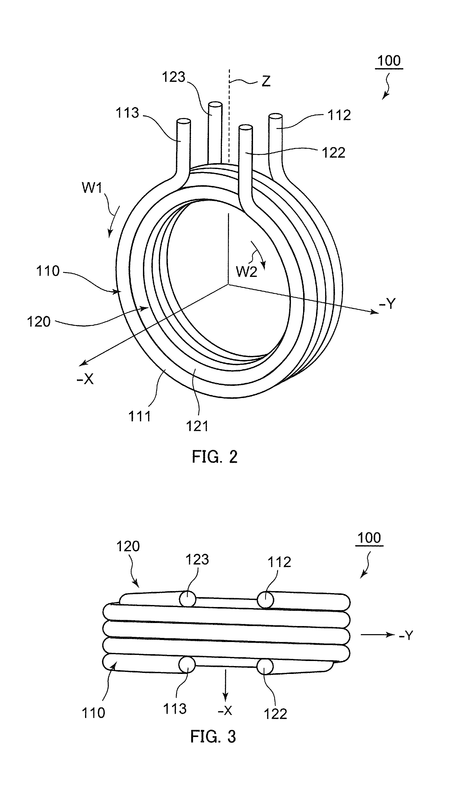
[0067]Combination torsion spring (hereafter, referred to as “combination spring”) 100 shown in FIG. 2 and FIG. 3 includes first torsion spring 110 and second torsion spring 120. Note that, in FIG. 2 and FIG. 3, combination spring 100 is shown as a combination spring that is in a predetermined attachment state.
[0068]First torsion spring 110 and second torsion spring 120 include coil sections 111 and 121, respectively, that are formed by winding steel wires in a helical shape in mutually different winding directions. In this case, as viewed from an X-direction side, coil section 111 of first torsion spring 110 is formed in a tubular shape by winding a steel wire in a helical shape in the clockwise direction (W1 direction) from one end (end on a side of hook section 113 that is described below). On the other hand, coil section 121 of second torsion spr...
PUM
 Abstract
Description
Claims
Application Information
 - Generate Ideas
- Intellectual Property
- Life Sciences
- Materials
- Tech Scout
- Unparalleled Data Quality
- Higher Quality Content
- 60% Fewer Hallucinations
Browse by: Latest US Patents, China's latest patents, Technical Efficacy Thesaurus, Application Domain, Technology Topic, Popular Technical Reports.
© 2025 PatSnap. All rights reserved.Legal|Privacy policy|Modern Slavery Act Transparency Statement|Sitemap|About US| Contact US: help@patsnap.com