Beam steering antenna structure

a technology of beam steering and antenna structure, which is applied in the direction of individual energised antenna arrays, antennas, electrical devices, etc., can solve the problems of greater power energy consumption, achieve effective power energy saving, reduce hardware requirements, and consume greater power energy

Active Publication Date: 2013-09-12
NAT CHIAO TUNG UNIV
View PDF4 Cites 15 Cited by
  • Summary
  • Abstract
  • Description
  • Claims
  • Application Information

AI Technical Summary

Benefits of technology

[0012]Compared to prior techniques, the beam steering antenna structure of the invention has relatively lower demands for hardware as it does not require the steering of phases in every antenna element, and also its major advantage lies in its capability of effective saving of power energy since it provides bias voltages to the transistors for enabling the continuance of the metallic units only in the direction of transmission or reception of electromagnetic waves. In contrast, the conventional art employs the concept of electromagnetic gap in which the electromagnetic waves radiate toward the direction of the metallic wires containing light emitted diodes without bias voltages, and the remaining metallic wires with bias voltages form a reflective surface to block out electromagnetic waves and thus consume greater power energy as a result.

Problems solved by technology

In contrast, the conventional art employs the concept of electromagnetic gap in which the electromagnetic waves radiate toward the direction of the metallic wires containing light emitted diodes without bias voltages, and the remaining metallic wires with bias voltages form a reflective surface to block out electromagnetic waves and thus consume greater power energy as a result.

Method used


Image

  • Beam steering antenna structure
  • Beam steering antenna structure
  • Beam steering antenna structure

Examples


Embodiment Construction

[0023]The following illustrative embodiments are provided to illustrate the disclosure of the present invention, these and other advantages and effects can be understood by persons skilled in the art after reading the disclosure of this specification. Note that the structures, proportions, sizes depicted in the accompanying figures merely serve to illustrate the disclosure of the specification to allow for comprehensive reading without a limitation to the implementation or applications of the present invention, and does not constitute any substantial technical meaning. Also, the expressions and terms quoted in the specification including “length,”“width” and “angle” are illustrative but not restrictive, and may encompass alterations or adjustments of its relative relations without substantially altering the technical contents contained therein.

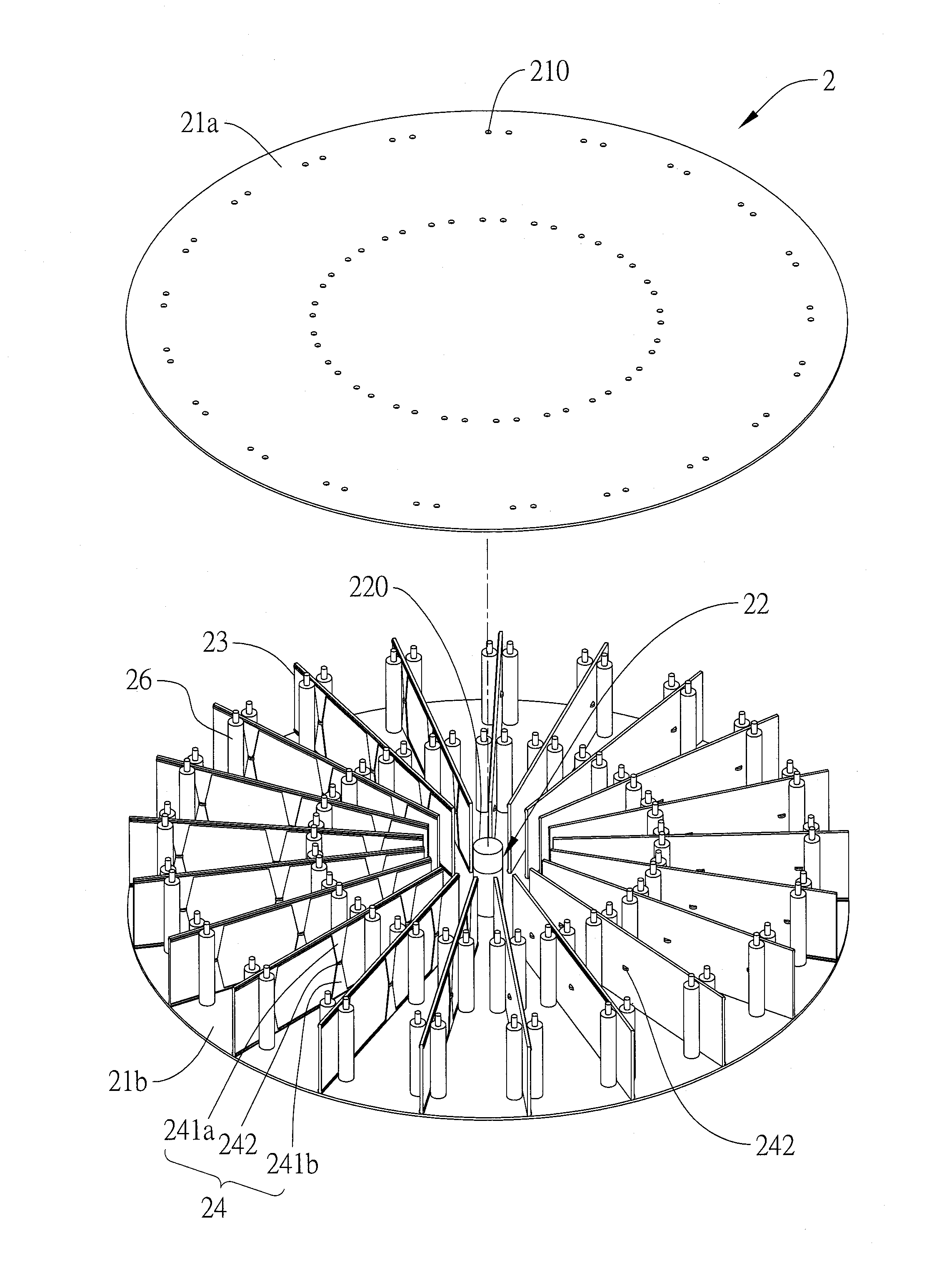
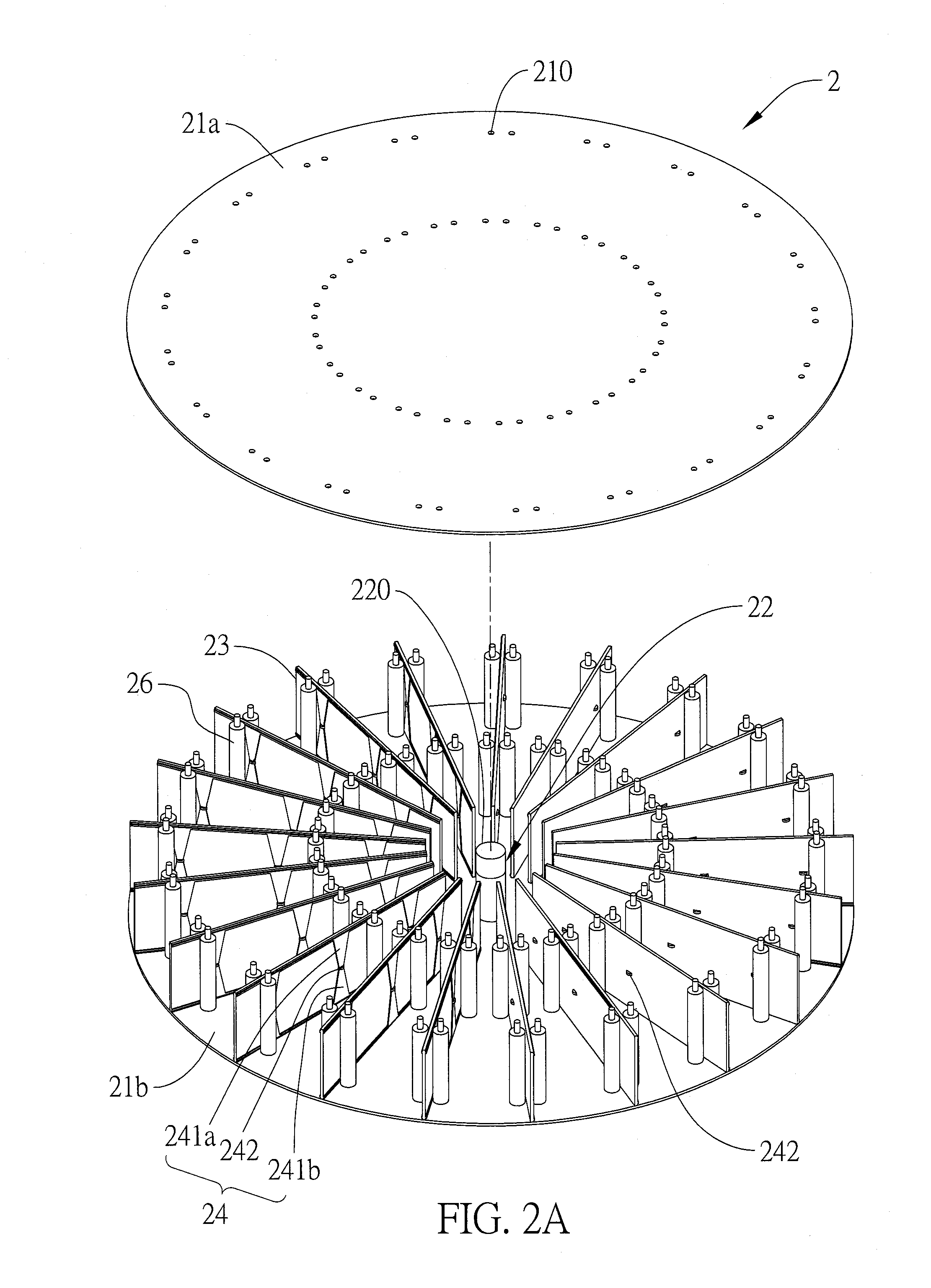
[0024]Referring to FIGS. 2A and 2B, a beam steering antenna structure 2 comprises two metallic boards 21a and 21b, an antenna 22, multiple su...


PUM


Abstract

Disclosed is a beam steering antenna structure, including two parallel metallic boards, an antenna perpendicularly disposed between the two metallic boards, a plurality of substrates perpendicularly disposed between the two metallic boards and radially disposed around the antenna, and a bias voltage circuit. Each of the substrates has a plurality of metal units cyclically aligned thereon, and each of the metal units includes two metallic regions oppositely disposed and in no contact with each other and a transistor disposed between the two metallic regions for coupling the two metallic regions. The transistors are electrically connected to the bias voltage circuit to thereby control the steering direction of beam radiation by switching the transistors.

Description

BACKGROUND OF THE INVENTION[0001]1. Field of the Invention[0002]The present invention relates to antenna structures, and, more particularly, to a beam steering antenna structure.[0003]2. Description of Related Art[0004]The transmission paths of electromagnetic waves often encounter the blockage of large building in cities and thus result in multi-path fading. As such, presently there exist many technical improving means and the so-called Smart Antenna has become mainstream that is designed to eliminate the transmission blockage mentioned above.[0005]Smart antennas use the characteristic of Spatial Diversity to differentiate users and signals from different locations / positions for achieving the diversity gain. In other words, Smart antennas use narrower beams for receiving and transmitting signals to obtain greater power for communication, whereas the signals transmitted within the range of non-narrow beams are suppressed by narrower beams, thus reducing the intensity of noise signal...

Claims


Application Information

Patent Timeline
Patent Type & Authority Applications(United States)
IPC IPC(8): H01Q3/00
CPCH01Q21/20H01Q3/242
Inventor HWANG, RUEY-BINGYANG, SU-CHEHUANG, HSIEN-TUNG
Owner NAT CHIAO TUNG UNIV
Why Eureka
Try Eureka