System and method for linking and controlling terminals

Inactive Publication Date: 2013-09-12
IUCF HYU (IND UNIV COOP FOUNDATION HANYANG UNIV)
View PDF6 Cites 17 Cited by
  • Summary
  • Abstract
  • Description
  • Claims
  • Application Information

AI Technical Summary

Benefits of technology

[0013]In a method and system for linking and controlling terminals according to an embodiment, the receiving terminal can provide the user terminal with an entire or a portion of a displayed image, the user can select an event-executing entity included in the image via the user terminal, and the user terminal can transmit the selection information of the event-executing entity to the receiving terminal. Thus, the user can efficiently control the operations of the receiving terminal by using the user terminal.
[0014]Since the image of the receiving terminal may be displayed on the user terminal, the user can control the receiving terminal wit

Problems solved by technology

However, it is inconvenient for a user to control a smart TV using touch met

Method used


Image

  • System and method for linking and controlling terminals
  • System and method for linking and controlling terminals
  • System and method for linking and controlling terminals

Examples


first embodiment

[0079]FIG. 2A and FIG. 2B illustrate a method of linking and controlling terminals according to a

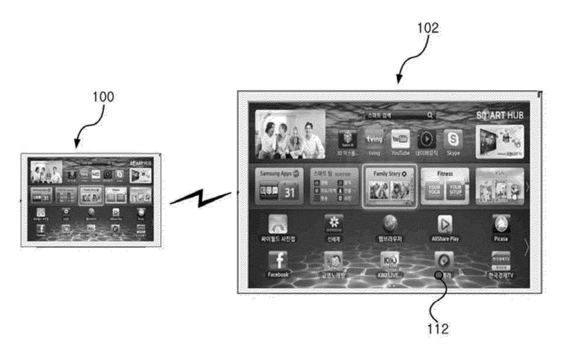
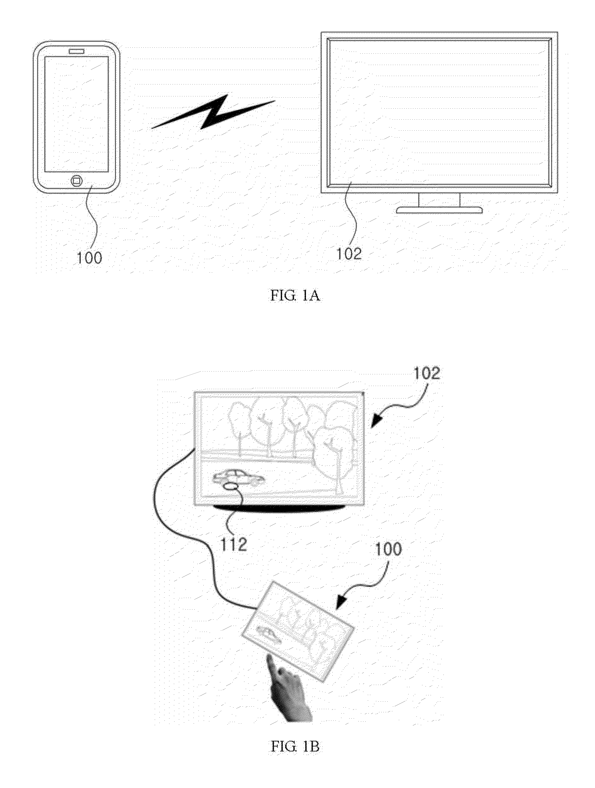
[0080]Referring to FIG. 2A, the receiving terminal 102 can transmit image data corresponding to a first image 110 that includes an event-executing entity 200, such as a UI, icon, application program, link, etc., for example, to the user terminal 100. Consequently, the first image 110 displayed on the user terminal 100 can include the event-executing entity 200.

[0081]According to an embodiment, when the user touches the event-executing entity 200 with a touch means, the user terminal 100 can transmit selection information, which notifies that the event-executing entity 200 was selected, to the receiving terminal 102. The selection information can include position infoll tation corresponding to a touch input for selecting the event-executing entity 200 or, depending on the touch input, control information for executing the event-executing entity 200.

[0082]The receiving terminal 102 can rec...

second embodiment

[0085]FIG. 3 illustrates a method of linking and controlling terminals according to a

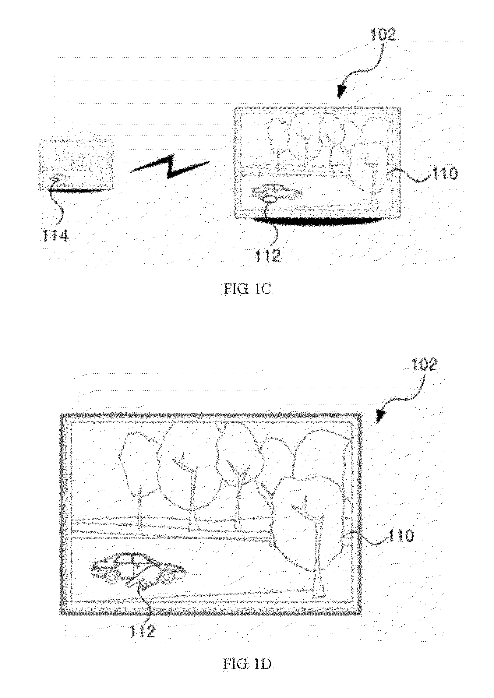
[0086]Referring to FIG. 3, it is also possible to transmit to the user terminal 100 only the image 300 corresponding to a UI for control from among the first image 110 displayed on the receiving terminal 102, so that the user terminal 100 can display a corresponding image 302. That is, the user terminal 100 and the receiving terminal 102 can share just a portion of the image, especially a portion including an event-executing entity. In this case, a second image 112 indicating the position of the touch means may be displayed on the receiving terminal 102. Of course, a third image 114 indicating the position of the touch means can also be displayed on the user terminal 100, where the third image 114 can be substantially the same as the second image 112.

[0087]In such a linkage system, when the user touches an event-executing entity in the image 302 displayed on the user terminal 100 with a touch means,...

third embodiment

[0090]FIG. 4A and FIG. 4B illustrate a method of linking and controlling terminals according to a

[0091]Referring to FIG. 4A and FIG. 4B, the image for the second image 112a indicating the position of the touch means can be changed to a different shape. Also, the second image 112a can be changed if the touch means is present at a preset position while it is near the user terminal 100 or is touching the user terminal 100 with a pressure or an area smaller than or equal to a preset pressure or area level.

[0092]For example, if the touch means is not positioned over an event-executing entity, the second image 112a can be represented as a shadow image as illustrated in FIG. 4A, but if the touch means is positioned over an event-executing entity, it can be represented by a finger image as illustrated in FIG. 4B. The second image 112 can be changed when the touch means is positioned not only over an icon, but also over an Internet address input window, the bottom of the screen, a search win...


PUM


Abstract

A system for linking and controlling terminals is disclosed. The user terminal includes a decoding unit configured to decode image data received from a receiving terminal; a touch display unit configured to display the decoded image; and an information transmitting unit configured to transmit selection information for an event-executing entity included in the decoded image to the receiving terminal.

Description

CROSS-REFERENCE TO RELATED APPLICATIONS[0001]This application claims the benefit of Korean Patent Applications No. 10-2012-0023012, No. 10-2012-0022986, No. 10-2012-0022988, No. 10-2012-0022984, No. 10-2012-0024073, No. 10-2012-0024092, No. 10-2012-0032982, No. 10-2012-0033047, No. 10-2012-0043148, No. 10-2012-0057996, No. 10-2012-0057998, No. 10-2012-0058000, filed respectively with the Korean Intellectual Property Office on Mar. 6, 2012, Mar. 6, 2012, Mar. 6, 2012, Mar. 6, 2012, Mar. 8, 2012, Mar. 8, 2012, Mar. 30, 2012, Mar. 30, 2012, Apr. 25, 2012, May 31, 2012, May 31, 2012, May 31, 2012, the disclosures of which are incorporated herein by reference in their entireties.BACKGROUND[0002]1. Technical Field[0003]The present invention relates to a system and method for linking and controlling terminals.[0004]2. Description of the Related Art[0005]The smart TV has become very popular in recent times, and various methods have been proposed to increase convenience in performing operati...

Claims


Application Information

Patent Timeline
IPC IPC(8): G06F3/0488
CPCH04N2005/441H04N2005/4425H04N2005/443G06F3/0488G06F3/0412G06F9/4445H04N21/42224H04N5/4403G06F2203/0384H04N21/42207H04N21/42209H04N21/4222G06F3/038G06F3/0416G06F9/452H04N21/41265H04N21/42204G06F3/1423G06F3/16
Inventor YOO, CHANG-SIK
Owner IUCF HYU (IND UNIV COOP FOUNDATION HANYANG UNIV)
Why Eureka
Try Eureka