Camera system for three-dimensional thermal imaging

a three-dimensional thermal imaging and camera system technology, applied in the field of three-dimensional camera systems, can solve the problems of two cameras, non-uniformity, and inability to couple thermal imaging data with 3d stereo image data, and achieve the effect of the same performan

Active Publication Date: 2013-09-12
JOO HOON
View PDF9 Cites 55 Cited by
  • Summary
  • Abstract
  • Description
  • Claims
  • Application Information

AI Technical Summary

Benefits of technology

[0010]In the present disclosure described above, since one of right and left thermal imaging cameras has a master function and the other thermal imaging camera has a slave function, a master thermal imaging camera plays a role of providing various references, and the slave camera is adjusted with reference to the reference data of the master camera so that both thermal imaging cameras resultantly have the same performance. Accordingly, since both cameras may ensure the matched performance by based on matched functioning, it is possible to provide a 3D stereo thermal image and distance / depth data. In addition, since a separate camera having a master function may plays a role of various references, two thermal imaging cameras may ensure matched performance and provide a 3D stereo thermal image and distance / depth data.

Problems solved by technology

However, there has been no attempt to couple thermal imaging data with 3D stereo image data so far.
In order to couple 3D stereo image data and thermal imaging data, various problems should be solved, and the most important problem is that a target should be photographed simultaneously and accurately by using two thermal image cameras with the identical performance.
However, since individual temperature sensor elements respond to a surrounding temperature and a target temperature in different ways, non-uniformity phenomenon occurs and so images photographed by two cameras may be different.
In other words, since detectors of a camera have different gain and offset in the temperature sensor array, thermal images obtained by two cameras become different, and so it is impossible to implement a proper 3D stereo thermal image.

Method used


Image

  • Camera system for three-dimensional thermal imaging
  • Camera system for three-dimensional thermal imaging
  • Camera system for three-dimensional thermal imaging

Examples


Embodiment Construction

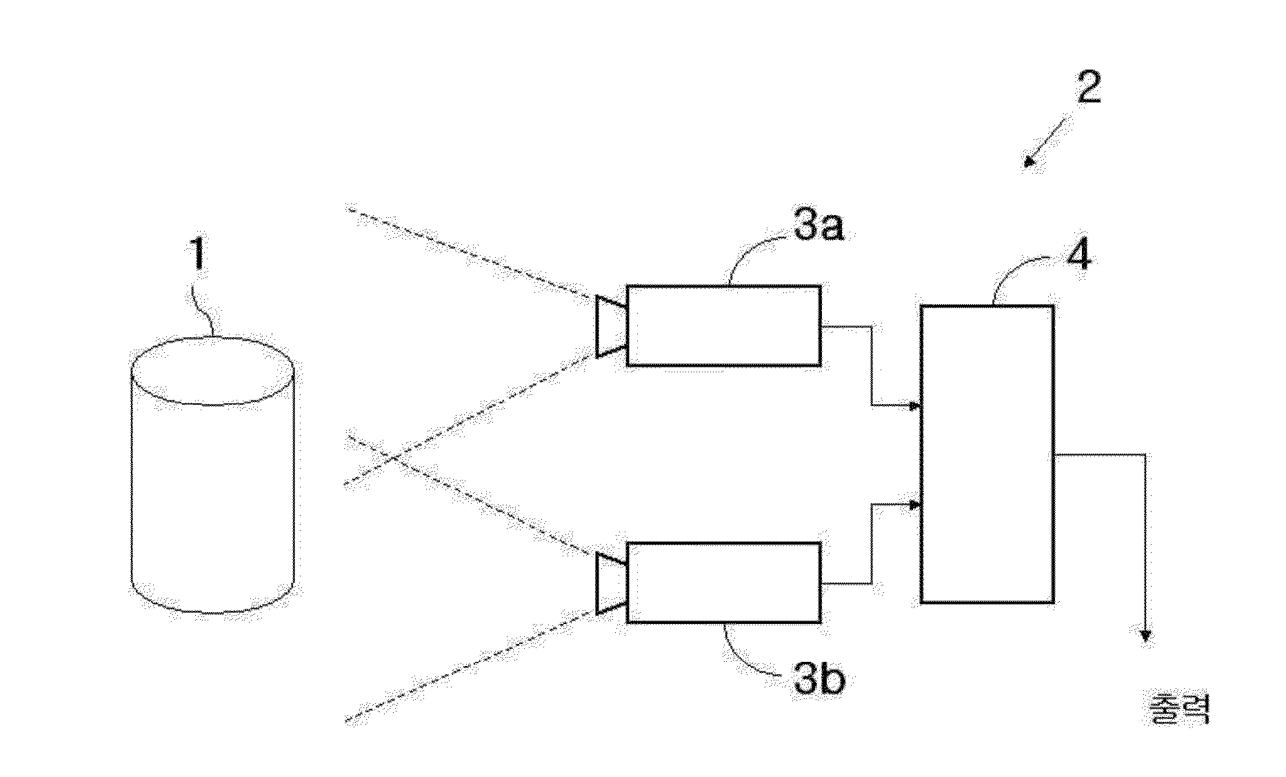
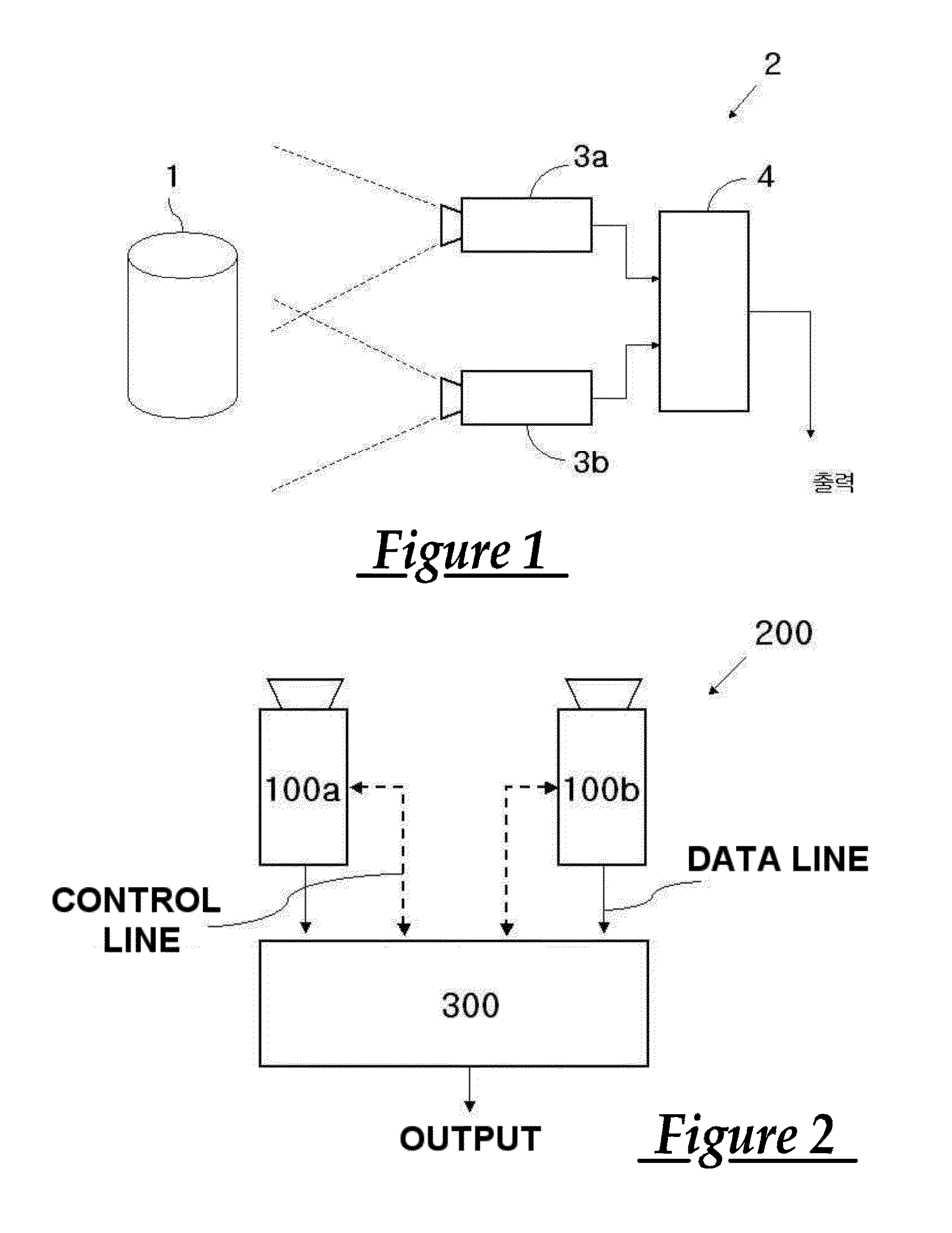
of Main Elements]1: target (subject)3a, 3b: camera4: controller100a, 100b: thermal imaging camera200: 3D stereo image camerasystem300: stereo & disparity engine

BEST MODE

[0021]Hereinafter, the embodiments of the present disclosure will be described in detail with reference to accompanying drawings.

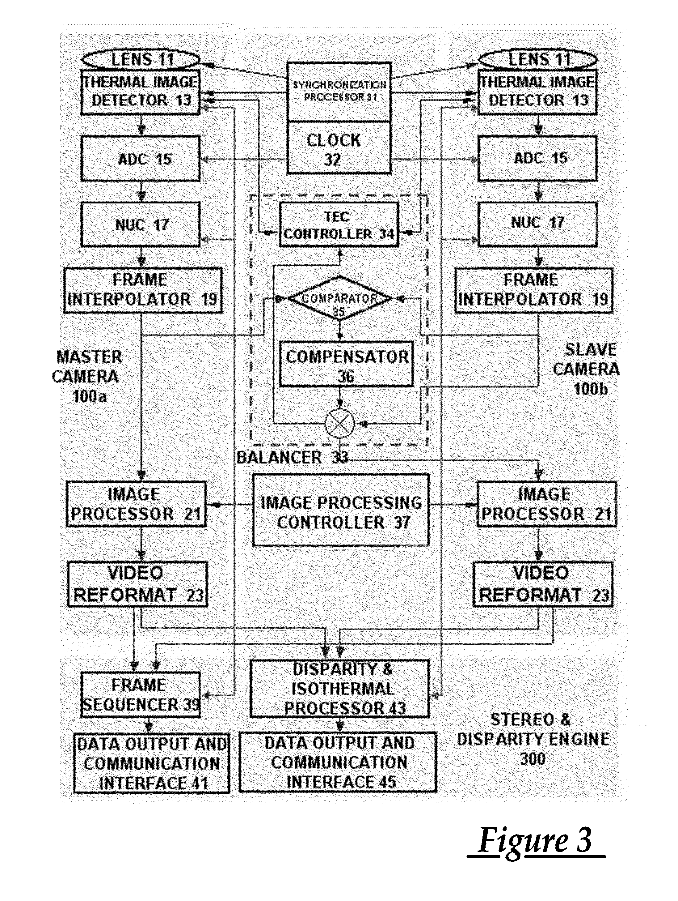
[0022]FIG. 2 schematically shows a 3D thermal imaging camera system according to an embodiment of the present disclosure. The 3D thermal imaging camera of the present disclosure includes right and left cameras 100a, 100b, in which one is a master camera serving as a mater and the other is a slave camera serving as a slave. Either of the cameras may be selected as a master according to the working environments where the camera system of the present disclosure is implemented. In the embodiment of the present disclosure, the left camera 100a is selected as a master camera, and the right camera 100b is selected as a slave camera. In addition, the basic concept of the present disclosure is not c...


PUM


Abstract

Provided is a system for displaying a 3D thermal image by using two thermal imaging cameras and extracting distance/depth data in the thermal images. The system includes two thermal imaging cameras where one thermal imaging camera is used as a master camera serving as a reference and the other is used as a slave camera to correct gain and offset of the thermal images and ensure uniformity. In addition, provided is an apparatus and method for correcting gain and offset of the thermal images to be identical to each other and ensuring uniformity by using a process module separately from two thermal imaging cameras.
Therefore, since temperature data is overlaid on the 3D thermal image or the thermal imaging data from which disparity from two cameras is extracted, it is possible to provide more accurate and diverse subject recognition information in comparison to an existing device which provides just a 3D image or an infrared image solely.
In addition, since temperature data is overlaid on a 3D thermal image or the thermal imaging data from which disparity from two cameras is extracted by processing only data about a partial area of interest (temperature area, image area) among the entire thermal image for the purpose of high-speed frame processing, it is possible to rapidly provide more accurate and diverse subject recognition information in comparison to an existing device which provides just a 3D image or an infrared image solely.

Description

TECHNICAL FIELD[0001]The present disclosure relates to an apparatus for making and displaying a 3-dimensional (3D) stereo thermal image by using a thermal imaging camera and an apparatus and method for extracting distance and depth data from two thermal imaging cameras, and more particularly, to a 3D stereo thermal imaging camera system manufactured by coupling a 3D thermal imaging camera with two 2D thermal imaging cameras and a method for photographing and processing a 3D stereo thermal image by using the system.BACKGROUND ART[0002]Recently, the techniques for providing 3D stereo images on a screen rapidly increase in various fields such as movies, broadcasting, game or the like. Generally, the terms “3D image” and “3D stereo image” are confusedly used, but strictly speaking, these terms are entirely different from each other. The term “3D image” represents a planar image showing all of x, y and z axes on a general 2D display, and the term “3D stereo image” represents an image imp...

Claims


Application Information

Patent Timeline
Patent Type & Authority Applications(United States)
IPC IPC(8): H04N13/02
CPCH04N13/007G03B35/08G06F3/011H04N13/0239H04N13/239H04N13/183
Inventor JOO, HOON
Owner JOO HOON
Why Eureka
Try Eureka